T i u, Lî il – Carrier 09DK054-084 User Manual
Page 14
Attention! The text in this document has been recognized automatically. To view the original document, you can use the "Original mode".
084 Units
FCPS2-
ZI..........
........O
t i U
100
%
FCPS1
FCPS2■
...................■ T"'"! r—^
1 '
1
»
•
i
l
l
*
1
1
1
1
1
1
1
1
1
1
!
I
:
!
!
!
H
li
—-O- - L _
ÎÜ
50% / 50%
FCPS1
O
FCPS2 ■
[4
■O
î
FCPS4
lî il
33%
67%
FCPS1
FCPS2
r---0
FCPS2
FCPS4
FCPS3
Î !i
|-0
__ a __ a_
33%
î a
17%
Î !
17%
O- -1
¡1
33%
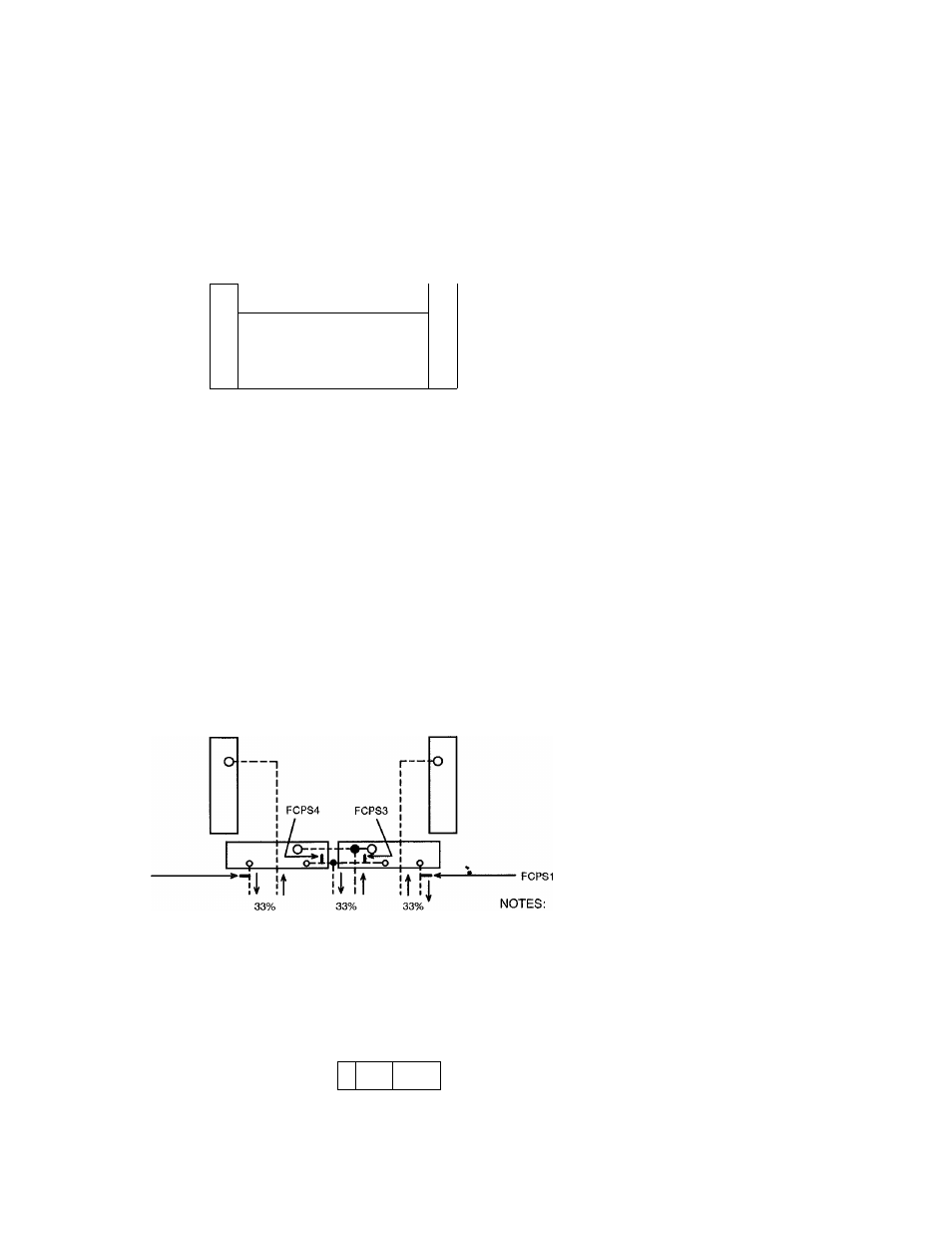
FCPS
— Fan Cycle Pressure Switch
1 FCPS1 = Fan cycle pressure switch 1 cycles fan 3 in
response to condensing pressure.
2 FCPS2 = Fan cycle pressure switch 2 cycles fan 4 in
response to condensing pressure
3. FCPS3 = Fan cycle pressure switch 3 cycles fan 3 in
response to condensing pressure.
4. FCPS4 = Fan cycle pressure switch 4 cycies fan 4 in
response to condensing pressure
5. In the above applications where a fan is being shared by two
different refrigeration circuits, the FCPSs (FCPS1 and 3 or
FCPS2 and 4) are in parallel so that if either circuit needs the
fan to be on, it will be on.
FCPS1
Fig. 8 — Typical Field Piping Arrangements (cent)
14