Carrier 09DK054-084 User Manual
Page 27
Attention! The text in this document has been recognized automatically. To view the original document, you can use the "Original mode".
NOTES:
1. Factory wiring is in accordance with National Electrical Code (NEC),
field modifications or additions must be in compliance with all ap
plicable codes.
2. Wiring for field power supply must be rated 75 C minimum. Use
copper, copper-clad aluminum, or aluminum conductors. Maxi
mum incoming wire size for each terminal block is 2/0.
3. Terminal blocks TB2, TBS, TB4, TBS, TB6, and TB7 are for
external field control connections. Control connections are to be
class 1 wiring.
4. Replacement of factory wires must be with type 105 C wire or its
equivalent.
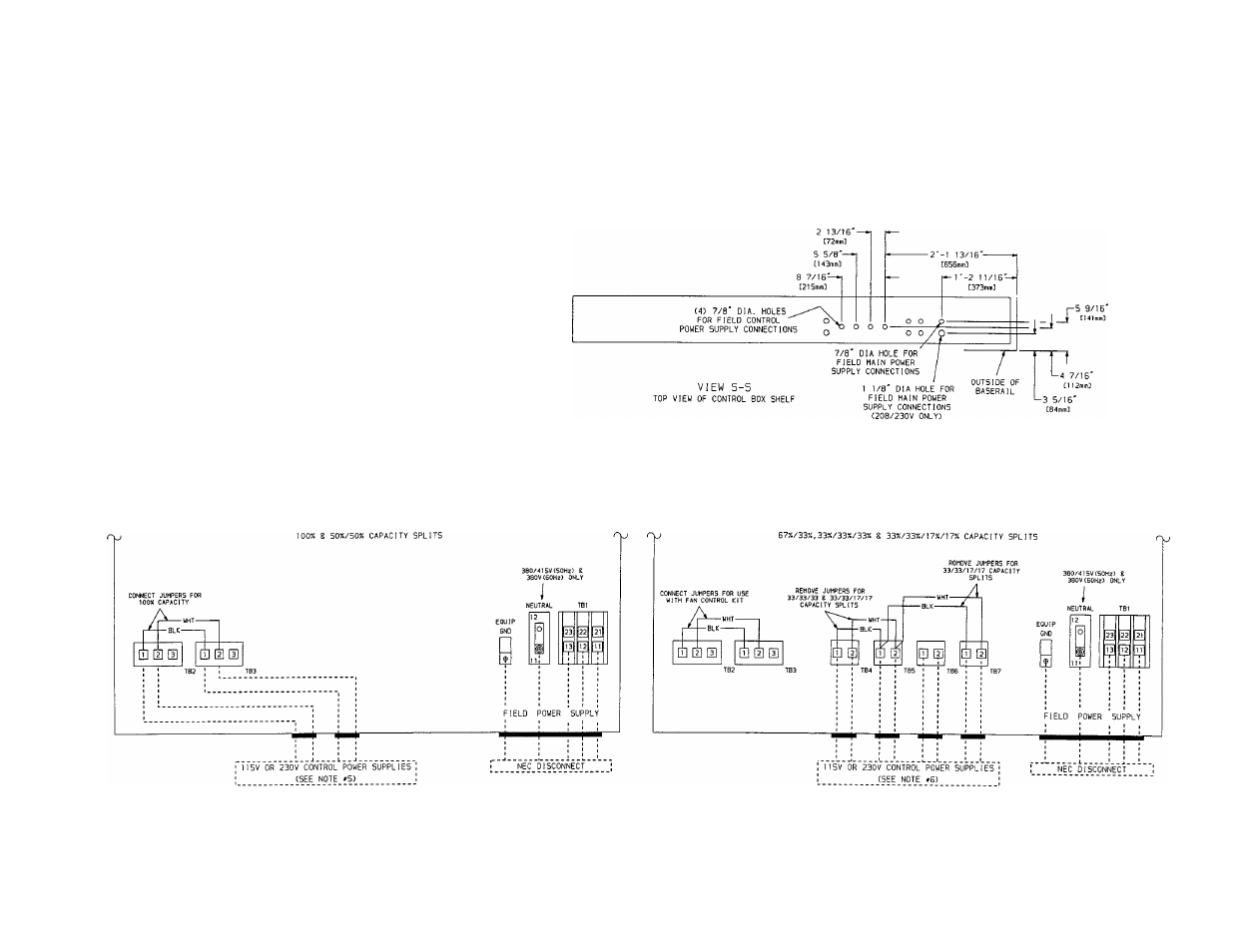
5. Units are factory wired for a 50%/50% capacity split. If 100% ca
pacity is required, connect the factory-supplied jumpers from TB2-1
to TB3-1 and from TB2-2 to TB3-2.
6. If a fan control kit is to be used, the jumper from TB2-1 to TB3-1
and the jumper from TB2-2 to TB3-2 must be connected. The
fan control kit is factory wired for a 67%/33% capacity split. If a
33%/33%/33% capacity split is required, remove the jumper from
TB4-1 to TB5-1 and from TB4-2 to TB5-2. If a 33%/33%/17%/17%
capacity split is required, remove the jumpers from TB4-1 to TB5-1
to TB7-1 and from TB4-2 to TB5-2 to TB7-2.
K)
CONTROL BOX
STANDARD UNITS
CONTROL BOX
UNITS WITH FAN CONTROL LIT tACCESSORV)
Fig. 25 — Field Wiring; 054-084 Units