Carrier 09DK054-084 User Manual
Page 16
Attention! The text in this document has been recognized automatically. To view the original document, you can use the "Original mode".
100% Coil Circuiting Applications: 084 Units
1. Piping —
Refer to Fig. 9 and 21 for field piping details
for 100% coil circuiting. Note that tubes 16 and 20 require
a cut on the longer leg of the tubes. Two 7/8-in. OD tubes,
approximately 3 in. (72.6 mm) long, must be cut from the
remaining tubes (22 or 23) and brazed between the tees
(item 9) and coil header stubs. The remaining tubes are not
used in this application and may be discarded.
2. Install Fan Cycle Pressure Switches and Clamps — Braze 2
valve core bodies to designated hole locations on tubes 20
and 24. Insert valve cores into valve core bodies by thread
ing into place and tightening to 1 5 to 3 in.-lb (169.5 to
339 mN-m) Install FCPSl and FCPS2 at designated loca
tions on tubes 20 and 24. Cut the 3/8-in. field-supplied FCPS
conduit at a desired length to fit between each FCPS loca
tion and the junction box on the unit. See Fig. 11 for typ
ical conduit installation. Feed FCPS wires through each conduit
and secure at the switch by utilizing each conduit connec
tor. See Fig. 13. Secure the conduit at the junction box
with 3/8-in. field-supplied conduit connectors. Wire FCPSl
and FCPS2 according to Fig. 18. At the location specified
in Fig. 21, clamp hot gas line, tube 28, using 2 1/8-in.
clamp and 2 screws provided. Clamp the liquid line, tube
25, using 1 1/8-in. clamp and 2 screws provided.
50/50% Coil Circuiting Applications: 084 Units
1. Piping
— Refer to Fig. 9 and 22 for field piping details
for 50/50% coil circuiting. Note that tube 20 requires a cut
on the longer leg of the tube. Tube 23 will require a cut
located exactly at the location of the hole in the tube, and
will be used at the two locations specified. Two 7/8-in. OD
tubes, approximately 3 in. (72.6 mm) long, must be cut
from the remaining tubes (22, 26, and 27) and be brazed
between the tees (item 9) and coil header stubs. The re
maining tubes are not used in this application and may be
discarded.
2. Install Fan Cycle Pressure Switches and Clamps — Braze 2
valve core bodies (item 6) to designated hole locations on
tubes 20 and 24. Insert valve cores (item 7) into valve core
bodies by threading into place and tightening to 1.5 to
3 in.-lb (169.5 to 339 mN-m). Install FCPSl and FCPS2
(item 8) at designated locations on tubes 20 and 24. Cut the
3/8-in. field-supplied FCPS conduit at a desired length to
fit between each FCPS location and the junction box on the
unit. See Fig. 11 for typical conduit installation. Feed FCPS
wires through each conduit and secure at the switch by us
ing each conduit connector. See Fig. 13. Secure the con
duit at the junction box with 3/8-in. field-supplied conduit
connectors. Wire FCPSl and FCPS2 according to Fig. 18.
At the location specified in Fig. 22, clamp hot gas line,
tube 16, using two 1 5/8-in. clamps and 4 screws provided.
Clamp the liquid lines, tubes 23, using two 7/8-in. clamps
(item 1) and 4 screws provided.
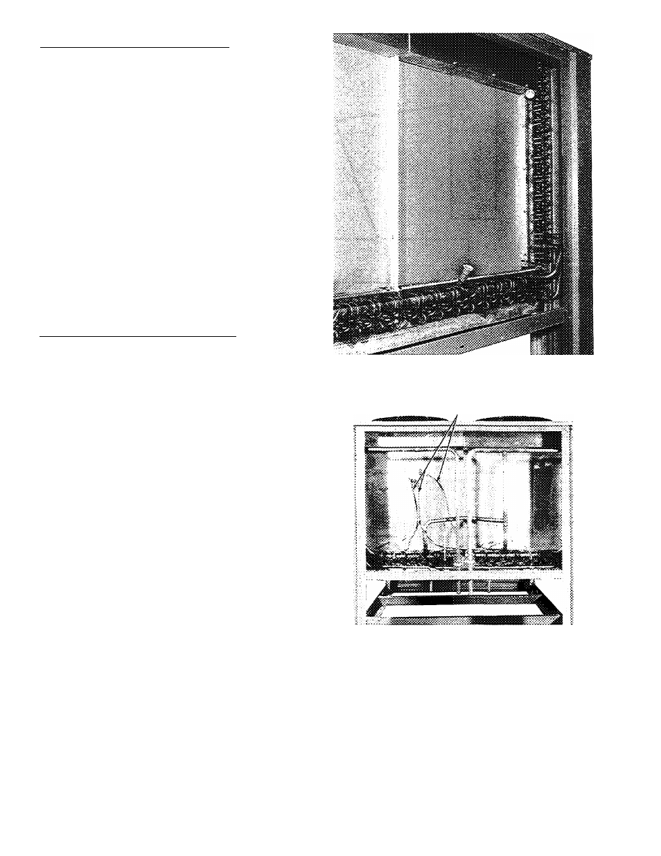
Fig. 10 — Typical Factory-Supplied Coil Circuiting,
09DK054-084 Units (084 Shown)
CONDUITS
Fig. 11 — Typicai Coil Circuiting for 09DK054-084
Units (67/33% Split Option; 084 Unit Shown)
16