Itii, U !t ii it, Î|-0 __ a.__a – Carrier 09DK054-084 User Manual
Page 13: T a ¡i
Attention! The text in this document has been recognized automatically. To view the original document, you can use the "Original mode".
o-
074 Units
— o
FCPS2■
;i..........
FCPS1
I
100
%
i i
o
--------------------------■ ?—1
^
--------------------------------------
l
i
l
i
i
l
l
'
1
1
1
>
1
1
1
>
1
1
1
1
I
I
I
i
l
l
1
1
1
1
FCPS2■
Jí
FCPS1
tij
50% / 50%
FCPS2•
O-------- 1
r
0
fel.
V
1 FCPS4
I I
Í
4
■o
FCPS1
32%
itii
68%.
FCPS2-
o
---------- 1
1
1
1-----
1
1
o
1
1
1 FCPS4
1 ,
1 /
1
1
FCPS3 1
\ 1
r---0
U !t ii It
32%
36%.
\r\
FCPS1
32%
FCPS2
FCPS4
FCPS3
1—0
Î
|-0
__ a.__a_
O - -
t a ¡i
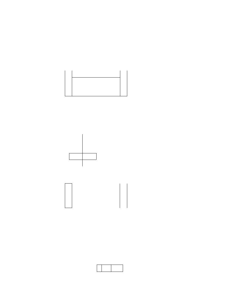
NOTES:
1 FCPS1 = Fan cycle pressure switch 1 cycles fan 3 in
response to condensing pressure.
2. FCPS2 = Fan cycle pressure switch 2 cycles fan 4 in
response to condensing pressure
3. FCPS3 = Fan cycle pressure switch 3 cycles fan 3 in
response to condensing pressure.
4. FCPS4 = Fan cycle pressure switch 4 cycles fan 4 in
response to condensing pressure
5 In the above applications where a fan is being shared by two
different refrigeration circuits, the FCPSs (FCPS1 and 3 or
FCPS2 and 4) are in parallel so that if either circuit needs the
fan to be on, it will be on
FCPS1
FCPS
32%
Fan Cycle Pressure Switch
18
%.
18%
32%
Fig. 8 — Typical Field Piping Arrangements (cent)
13