Carrier 09DK054-084 User Manual
Page 21
Attention! The text in this document has been recognized automatically. To view the original document, you can use the "Original mode".
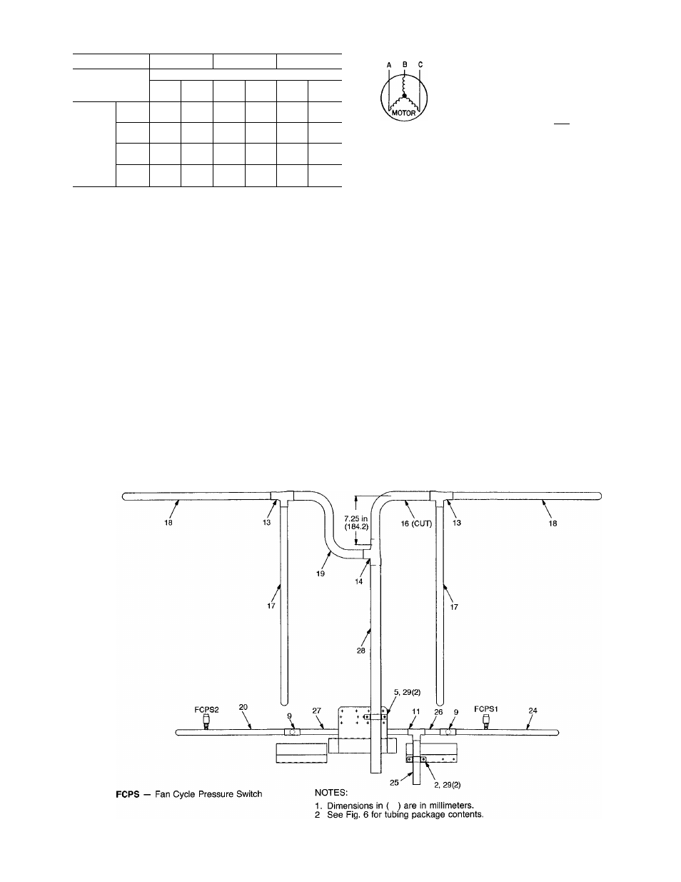
Table 3 — Available Liquid Lift Ft (m)
REFRIGERANT
R-22
R-502
R-134A
Temperature Difference F (C)
UNIT
20
(11.1)
30
(16.7)
20
(11.1)
30
(16.7)
20
(11.1)
30
(16.7)
054
60
(18.3)
50
(15 2)
60
(18.3)
44
(13.4)
29
(8.8)
26
(7.9)
09DK
064
41
(12 5)
31
(9.5)
41
(12.5)
25
(7 6)
20
(6.1)
6
(1.8)
074
44
(13.4)
34
(10.4)
44
(13.4)
28
(8.5)
18
(5.5)
7
(2.1)
084
51
(15.6)
41
(12.5)
51
(15.6)
35
(10.7)
22
(6.7)
10
(3 1)
NOTES:
1 The liquid lift data allows for a 7 psi (48 kpa) drop for liquid line
accessories, and a 2° F (1.rC), iiquid line ioss with maximum
change.
2. Temperature difference = Saturated condensing temperature (en
tering) — Entering-air temperature (dry buib) in degree F (° C)
3. The liquid iift data is based on 15° F (8 3° C) subcooiing, 95 F
(35 C) entering-air temperature, and a 50/50% capacity split ap-
piication Subcooling based on condenser subcooling = Satu
rated condensing temperature entering - Actual temperature leaving
the coii
Step 4 — Complete Electrical Connections
GENERAL — Verify nameplate electrical requirements match
available power supply. Voltage at condenser must be within
the minimum and maximum shown in Table 4 and phases
must be balanced within 2%. Contact local power company
for line voltage corrections. Never operate a motor where a
phase imbalance in supply voltage is greater than 2%.
Use the following formula to determine the percent voltage
imbalance:
max voltage deviation
% Voltage _
from average voltage
Imbalance
^ average voltage
Example: Supply voltage is 240-3-60.
AB = 243
V
BC = 236
V
AC = 238 V
Average Voltage
243 -F 236 -f 238
^ 717
3
= 239
V
Determine maximum deviation from average voltage:
(AB) 243 - 239 = 4 V
(BC) 239 - 236 = 3
V
(AC) 239 - 238 = 1
V
Maximum deviation is then 4 v. To determine the percent
voltage imbalance:
4
% Voltage Imbalance = 100 x----------
239
= 1.7%
This amount of phase imbalance is satisfactory since it is
below the maximum allowable of 2%.
IMPORTANT: If supply voltage phase imbalance is
more than 2%, contact your local electric utility com
pany immediately.
Condenser operation on improper line voltage or exces
sive phase imbalance may be considered abuse and any re
sulting damage may not be covered by Carrier warranty.
All wiring must be in accordance with local or NEC
(National Electrical Code) regulations.
FIELD CONNECTIONS - Refer to Table 4 and Fig. 14,
18, and 25 for field wiring details.
100
%
Fig. 17 - 100% Coil Circuiting; 074 Units
21