Fig. 13 — fan cycle pressure switch – Carrier 09DK054-084 User Manual
Page 18
Attention! The text in this document has been recognized automatically. To view the original document, you can use the "Original mode".
2. Install Fan Cycle Pressure Switches and Clamps — Four
FCPSs should be used. Locate holes, valve core assem
blies, and FCPS’s 1, 2, 3, and 4 at the specified locations.
See Fig. 8. Insert valve cores into valve core bodies by
threading into place and tightening to 1.5 to 3 in.-lb (169.5
to 339 mN-m). The additional two FCPSs and valve core
assemblies are provided with the accessory fan control kit.
Cut the 3/8-in. field-supplied FCPS conduit at a desired length
to fit between each FCPS location and the junction box on
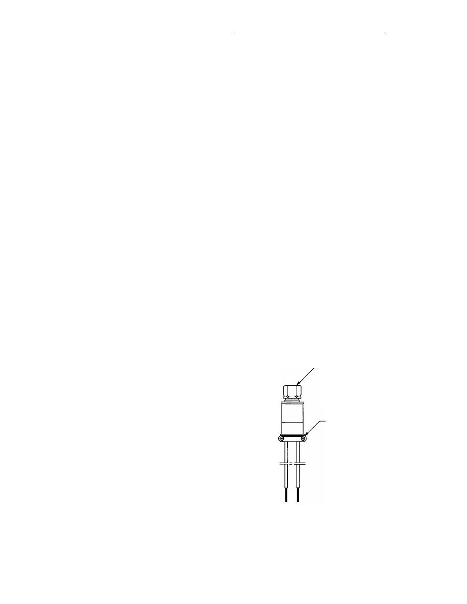
the unit. See Fig. 11 for typical conduit installation. Feed
FCPS wires through each conduit and secure at the switch
by utilizing each conduit connector. See Fig. 13. Secure
the conduit at the junction box with 3/8-in. field-supplied
conduit connectors. Wire the FCPSs according to Fig. 14
and 18. Note that FCPS2 and 4 and FCPSl and 3 are wired
in parallel. Fans 3 and 4 are being shared by two different
refrigeration circuits. If either refrigeration circuit needs the
fan to be on, it will be on. Clamp all lines to brackets sup
plied on the unit.
REFRIGERANT LINE SIZING - Sizing depends on length
of lines between various sections of the refrigerant system.
See Fig. 9 for coil connection details. Consider the amount
of liquid lift and drop in the system as well as proper com
pressor oil return. See Liquid Lift section for more infor
mation. Consult Carrier System Design Manual, Part 3, or
Carrier E20-II Refrigerant Piping Computer Program for proper
piping sizes and design
LIQUID SHUTOFF VALVE AND SIGHT GLASS - A
shutoff valve is not supplied with 09DK condensers. It is
strongly recommended that a full line size liquid shutoff
valve be field supplied near condenser to allow for servic
ing parts of the refrigerant circuit A field-supplied mois
ture indicating sight glass is recommended for use in charg
ing and servicing the system. Refer to Fig. 7.
PRESSURE RELIEF - The ASHRAE Standard 15, Safety
Code for Mechanical Refrigeration states; “Every refriger
ating system shall be protected by a pressure relief device
or some other means designed to safely relieve pressure due
to fire or other abnormal conditions ” Since 09DK con
densers do not have pressure relief devices, one must be
field supplied and installed just before the liquid line ser
vice valve. (See Fig. 7.) When the split coil is used with
multiple systems, each system must have its own pressure
relief.
REFRIGERANT RECEIVER — A refrigerant receiver is
not
furnished with 09DK condensers and is not recom
mended for normal applications as its use will be detrimen
tal to the desired effects of subcooling. However, if a par
ticular application requires a receiver to increase refrigerant
holding capacity of the condenser, a receiver can be used.
When a receiver is to be used year-round, it should be in
stalled indoors. Carrier recommends the following installa
tion in such a case (see Fig 24): locate valves on each side
of the receiver so receiver may be isolated from system for
normal operation.
Procedure for Using the Refrigerant Receiver — See
Fig. 24.
1. During normal operation — Valve A is open and valves
B and C are closed. Receiver is isolated from the
system.
2. For servicing — Valves A and C are closed and valve B
is open. Run unit until all the refrigerant is in the re
ceiver and then close valve B. Unit is now ready for ser
vicing.
3. To resume operation — Leave valve A closed and open
valves B and C. Run unit until the stored refrigerant is
drawn into the system. To completely remove the re
frigerant from the receiver, throttle valve B while noting
condition of refrigerant in the liquid line sight glass; also,
watch the suction pressure. A sudden surge of bubbles
in the sight glass and a rapid decrease in suction pres
sure indicates that all the refrigerant has been withdrawn
from the receiver. Immediately close valves B and C
and then open valve A. The unit should now be ready
for normal operation, with the receiver isolated from the
system. The system should be charged to a clear sight
glass when under normal operation.
LIQUID LIFT — Amount of liquid lift available before re
frigerant flashing occurs depends on amount of liquid sub
cooling in the system.
All 09DK condensers have positive subcooling when ap
plied with optimum charge. With subcooling, it is possible
to overcome an appreciable friction drop and/or static head
(due to elevation of the liquid metering device above the
condenser).
When 09DK condensers are applied with minimum charge,
no positive subcooling in condenser is realized; therefore,
if subcooling is required it must be obtained by external
means such as a liquid suction interchanger.
The average amount of liquid lift available is shown in
Table 3 for refrigerants R-22, R-502, and R-134A. Avail
able subcooling is greatly reduced when R-12 and R-500
are used in these units. It is recommended that the evapo
rator be at the same level as the condenser, or lower.
1/4 SAE FLARE WITH
56 (14 2) HEX
CONDUIT
CONNECTOR
SAE
— Society of Automotive Engineers
Fig. 13 — Fan Cycle Pressure Switch
18