Carrier 09DK054-084 User Manual
Page 28
Attention! The text in this document has been recognized automatically. To view the original document, you can use the "Original mode".
MAIN POWER WIRING — These units must have ade
quate overcurrent protection, fuses, or HACR (Heating, Air
Conditioning and Refrigeration) breakers, according to the
national and applicable local codes.
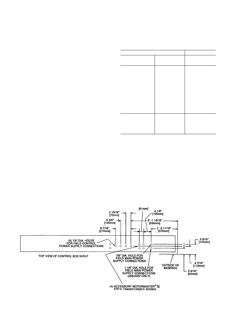
For field power connections, all main power wiring en
ters the unit through a factory-punched access hole under
the control box. Two access holes are provided, the larger
should be used for 208/230 v applications. See Fig. 26.
Wiring must be rated at 75 C minimum. Use copper, copper-
clad aluminum, or aluminum conductors. Field power sup
ply connections are made at terminal block 1 (TBl). Max
imum incoming wire size for each terminal connection on
TBl is 2/0, and all power wiring must comply with appli
cable local and national codes. Refer to the unit power cir
cuit information to determine incoming wire sizes. (See
Table 4.) Refer to Table 5 for American and European wire
conversion information.
CONTROL CIRCUIT POWER WIRING - Provide a sep
arate single phase power source for each control circuit (de
pending on the coil refrigerant circuit split), with the re
quired overcurrent protection (fuses or circuit breakers). See
Table 4 for control circuit overcurrent protection amps.
For field control circuit connections, units are factory wired
for a 50/50% capacity split and would utilize terminal blocks
2 and 3 (TB2 and TB3). TB2 will control fans 1, 3, and 5;
TB3 will control fans 2, 4, and 6. Fans 5 and 6 are on 074
and 084 units only. If 100% condenser application is re
quired, connect the factory supplied jumpers from TB2-1 to
TB3-1 and from TB2-2 to TB3-2, and bring incoming con
nections to either TB2 or TB3. Factory-punched access holes
under the control box are provided for the incoming wires.
See Fig. 26 for access hole details. Terminal block connec
tions utilize no. 8 screws. Wiring must be class 1, 14 AWG
(American Wire Gage) copper conductors only. Power re
quired for control circuits is 100 va. See Table 4 for control
circuit voltage data.
GENERAL WIRING NOTES
1. Power entry is at one end only.
2. Fan motors are thermally protected. Three-phase motors
are protected against primary single-phasing conditions.
3. Replacement of factory wires must be with appliance
wiring material, rated 105 C, or its equivalent.
4 Factory wiring is in accordance with NEC. Field mod
ifications or additions must be in compliance with all
applicable codes.
DESCRIPTION OF CONTROLS - The condenser units
utilize a dual voltage control scheme: a 3-phase power cir
cuit for the fan system operation and a single-phase control
circuit voltage for fan cycling control. The number of con
trol circuit voltages will depend on the coil split application
used. See head pressure control description in the service
section for a detailed description of the controls function.
Table 5 — American/European Wire Conversions
AMERICAN
EUROPEAN
Industry
Standard Size
American
Conversion
(mm^)
Industry
Standard
Size (mm^)
18 AWG
0.82
1.0
16 AWG
1 30
1.5
14 AWG
2.08
2.5
12 AWG
3 30
40
10 AWG
5 25
60
8 AWG
6.36
100
6 AWG
13.29
16.0
4 AWG
21.14
25.0
3 AWG
26.65
—
2 AWG
33.61
35 0
1 AWG
42.39
50.0
1/0 AWG
53.49
—
2/0 AWG
67.42
70.0
3/0 AWG
85.00
95.0
4/0 AWG
107.19
120.0
250 kcmil
126 64
150.0
300 kcmil
151 97
—
350 kcmil
177 90
185 0
400 kcmil
202 63
240 0
500 kcmil
253 29
300 0
600 kcmil
303 95
—
LEGEND
AWG —
American Wire Gage
kcmil —
Thousand Circular Mils
Step 5
—
Add Accessories As Needed
— The
following accessories are available for the 09DK054-084
condensers: fan sound reduction kit, condenser coastal coil
filter, security grille package, condenser coil hail guard pack
age, accessory control transformer, Motormaster® III de
vice, Motormaster III Relay/Sensor Kit, and accessory fan-
control kit. Winter Start and any special electrical interlock
must be considered separately. Refer to installation instruc
tions furnished with each accessory for more information.
2 13/32"
Fig. 26 — Power Wiring Access Holes; 054-084 Units
28