Ni to, Jn c – Carrier 09DK054-084 User Manual
Page 22
Attention! The text in this document has been recognized automatically. To view the original document, you can use the "Original mode".
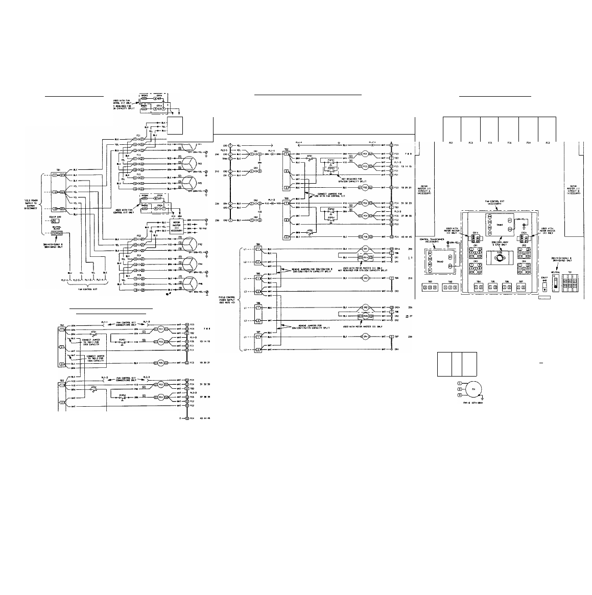
09DK074.0B4 POWER SCHEMATIC
Ni
to
COMCTIWS CN.T
09DK074.084 STANDARD CONTROL SCHEMATIC
(^00% 8 50X/50X CAPACITY SPLIT53
[|F PM nwrttx Ell IS USED. SEE PM CMTUX Ell (UCESSOftr) SCICIUtK)
FIELD COKlAa.
FUSTE»
230V CONTROL ONLY
FN, 3S §
- «CES50BT
- BBN TO FNI
cowccT Piuo Fca aeovtsoHz)
(H5V CWiaOL YOtTIGE 0*T
1
©o®
o
o
|o
®®®
o
®®®
o
«-.JL
—© ---------------------------------------------------- ----------- »--------HI —O FC3
^S0D---
090K074.084 FAN CONTROL KIT CACCESSORY^ SCHEMATIC
C67X/33-4.33X/33X/33X g 33X/33X/1 7X/1 7% CAPACITY SPLITS)
( D < D ( Z >
0
X
2)0
(KCESSoen
Jn C
NOTES:
1. Units are factory wired for a 50%/50% capacity split. If 100% capacity is required, con
nect the factory-supplied jumpers from TB2-1 to TB3-1 and from TB2-2 to TB3-2.
2. When a fan control kit is used, the jumper from TB2-1 to TB3-1 and from TB2-2 to TB3-2
must be connected. The fan control kit is factory wired for 67%/33% capacity split, if a
33%/33%/33% capacity split is required, remove the jumper from TB4-1 to TB5-1 and
from TB4-2 to TB5-2. If a 33%/33%/17%/17% capacity split Is required, remove the jump
ers from TB4-1 to TB5-1 to TB7-1 and from TB4-2 to TB5-2 to TB7-2.
3. On fan control kits, 208/230 v units are factory wired for 230 v power supply. For 208 v
power supply, connect yellow wire to terminal marked H2.
4. Terminal blocks TB2, TB3, TB4, TBS, TB6 and TB7 are for external field control connec
tions. Control connections are to be class 1 winng, 14 AWG copper conductors only.
5. Wiring for field power supply must be rated 75° C minimum. Use copper, copper-clad
aluminum, or alurTwnum conductors. Maximum incoming wire size for each terminal block
IS
2/0.
6. Replacement of factory wires must be with 105° C wire or its equivalent.
7. Factory wiring is in accordance with National Electncal Code (NEC). Field modifications
or additions must be in compliance with all applicable codes.
8. Fan motors are thermally protected. Three phase motors are protected against primary
single phasing conditions.
9. Line numbers on the left side of the label diagrams indicate the contact number. The
numbers on the nght side of label diagrams match the contacts with their corresponding
coils. A plain number indicates normally open contacts. An underlined number indicates
normally closed contacts.
Fig. 18 — Wiring Diagram and Component Arrangement; 074 and 084 Units
09DK074.0B4 COMPONENT ARRANGEMENT
O
FIELD CCmaOL PI
HNinOL BOX
0 o o
o o o
>m TE>MBlTL(lf SKITCK
COKTOOL RELIT
DLPTIT TERXINIL
' EauiPHENT
FIN CCMTICTOR
FICTWT II6IILLED S>1l<
lEmiNiL euXE
r~l TEftBlNAl ÍL0CE CC*»«CTIi»l
C
CONTROL EIT 0W.T)