Fig. 8, 0 t a – Carrier 09DK054-084 User Manual
Page 12
Attention! The text in this document has been recognized automatically. To view the original document, you can use the "Original mode".
054,064 Units
O-
.. .......... O
FCPS2■
FCPS2■
—*-o
i i
100
%
„1..
li
r—
o--*--o
til
50% / 50%
FCPS1
FCPS1
FCPS2•
O-------- T
1
--------
1
0
fel-
' ii
A
1 FCPS4
FCPS1
34%
66
%
FCPS2
FCPS2
FCPS4
FCPS3
1-0
t a
r-0
___a ----s_
O— -n
t-
t
ii
34%
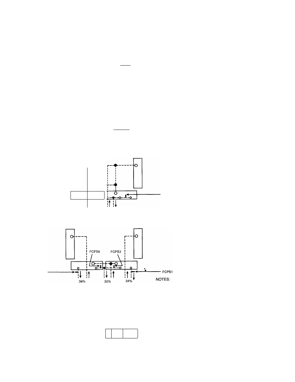
FCPS
— Fan Cycle Pressure Switch
16%
Fig. 8
16%
34%
1. FCPS1 = Fan cycle pressure switch 1 cycles fan 3 in
response to condensing pressure.
2. FCPS2 = Fan cycle pressure switch 2 cycles fan 4 in
response to condensing pressure.
3. FCPS3 = Fan cycle pressure switch 3 cycles fan 3 in
response to condensing pressure.
4. FCPS4 = Fan cycle pressure switch 4 cycles fan 4 in
response to condensing pressure.
5. In the above applications where a fan is being shared by two
different refrigeration circuits, the FCPSs (FCPS1 and 3 or
FCPS2 and 4) are in parallel so that if either circuit needs the
fan to be on, it will be on.
FCPS1
Typical Field Piping Arrangements
12