Top Flite TOPA0305 Part 2 User Manual
Page 31
3. With the wing attached to the fuselage, lift the
model at the balance point. We use the Great
Planes C.G. Machine
TM
(shown in the sketch) for
this. If the tail drops, the model is tail heavy and
you must shift your battery pack or other
components forward or add weight to the nose.
If
the nose drops, it is nose heavy and you must shift
your battery pack or other components aft or add
weight to the tail. In order to save weight, relocate
your battery pack and/or receiver or other
components before you add additional weight to
arrive at the correct C.G. You may easily install
nose weight by using a spinner weight or gluing
lead weights to the firewall. You may add tail
weight by sticking on Great Planes (GPMQ4485)
stick-on lead weights on the bottom of the fuselage
under the tail. Later, if the balance proves to be
OK,
you can open the fuse bottom and glue these
in permanently. Never stick weights to the cowl
because it is not designed to support weight.
BALANCE THE AIRPLANE
LATERALLY
1.
Mount your wing.
2.
With the wing level,
carefully lift the
model by the engine propeller shaft and the fin
or tail cone (this may require two people).
Do
this several times.
3.
If one wing always drops when you lift the
model, that side is heavy. Balance the airplane
by gluing weight inside the other wing tip.
An
airplane that has been laterally balanced will
track better in loops and other maneuvers.
INSTALL YOUR RECEIVER, BATERY
PACK AND RETRACT COMPONENTS
The location of your receiver and battery pack may
be determined by the C.G. On our prototypes we
mounted the battery pack and receiver nearly as
far forward as possible. With this arrangement, no
additional ballast was required to achieve the
recommended C.G. If this is where you wish to
mount your battery pack and receiver, you may use
the
mounting plates provided with this kit or
fashion your own method to secure your battery
pack and receiver.
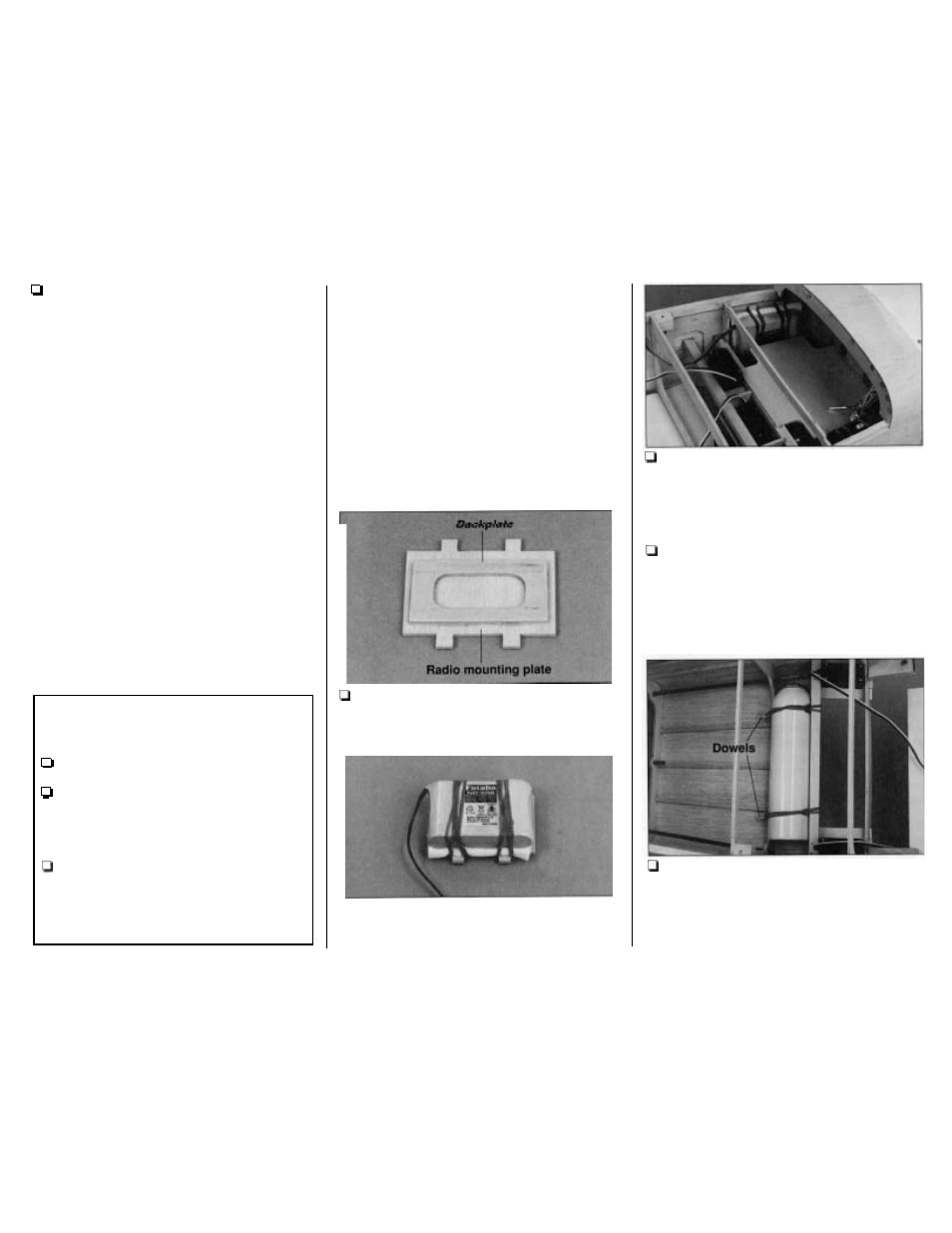
1.
Securely glue
a
die-cut 1/8" plywood plate
back to the die-cut 1/8"plywood radio mounting
plate.
2.
Secure your battery pack to the mounting
plate with
a
few rubber bands and 1/4" thick foam
rubber in between. Test fit the battery pack and
mounting plate in the front of the fuse as shown in
the photo.
Securely glue the mounting plate to the
fuse side doubler.
3. Install your receiver the same way. Route
your receiver antenna through the antenna tube.
Note: If in the future you have to remove, then
reinstall your receiver or battery pack, first hook the
rubber bands to the tabs on the mounting plate.
Next, stretch the rubber bands and slide your
battery pack and receiver underneath.
4.
Cut the two 1/8" x 1" dowels to a length of
3/4". Glue the dowels into the holes you drilled in
the bottom of former F6. Cut the aft edges of the
servo trays
so they are even with the servo rails.
Temporarily strap the air tank in place using two
rubber bands.
-
67
-