Top Flite TOPA0305 Part 2 User Manual
Page 22
aft cabin former and F7A. The thickness of the
cardboard should be approximately 1/64" or .015".
This is to provide a little clearance for painting and
covering. Trace the outline of F7A onto the piece of
cardboard. Cut approximately 1/4" outside of the
line you drew. Reposition the cardboard shim and
glue the aft cabin former to the crutch with the shim
in place.
11. Make a shim and glue the front cabin former
to the crutch the same way.
12.
Temporarily position some balsa sticks
between the front and aft cabin formers to make
sure they and the shims tightly contact the fuse.
You are going to fit the cabin top to the shims
so
the more accurately they fit the fuse, the more
accurately your cabin top will fit the fuse.
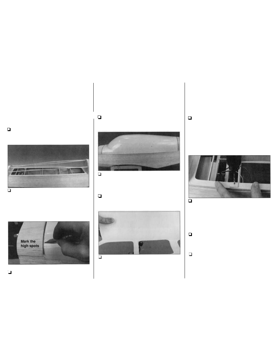
13.
Position the cabin top on the fuse so the
front contacts the cardboard shim and the
centerline on the cabin top aligns with the
centerline on the fuse. Use a lead pencil to mark
areas of the front of the cabin top that need to be
sanded for a perfect fit. Carefully
and
lightly sand
the areas you marked, erase the pencil marks, and
reposition the cabin top. Continue to mark, sand
and fit the cabin top until the front fits well.
14. Perform the same procedure to the aft edge
of the rear of the cabin top until it fits the rear
cardboard shim and the cabin top drops into place.
15.
With the cabin top on the fuse, make your
pencil marks where the bottom needs to be
trimmed. Sand the bottom edges of the cabin top
until it fits.
16. Thoroughly roughen the entire inside of the
cabin top with 220-grit sandpaper
so
glue and paint
will stick.
17.
Use a Dremel tool with a carbide cutter or a
similar type of rotary tool, or small scissors to cut
the window openings along the cutlines inside the
cabin top. The window outlines in the cabin top are
about 1
/16
smaller than the windows themselves.
This will allow you to accurately fit the windows
later, but do not enlarge the openings yet - just
roughlycut them along the cutlines for now.
MOUNT THE CABIN TOP
1. Remove the screws that temporarily hold the
crutch to the fuse.
Glue four
pieces of
3/4"
x 3/4" leftover 1/8" plywood to the crutch over
the holes. Using the holes in the crutch as a guide,
drill 1/16" holes up through the 1/8" ply pieces you
just glued on. Temporarily screw the crutch to the
fuse with the screws.
2. One at a time, remove a screw, and enlarge
the hole through the crutch and the blocks in the
fuse with a 1/8" drill. After you drill each hole
temporarily insert a 4-40
x 3/4" Phillips head screw
to hold the crutch in alignment as you drill the rest
of the holes.
3. Remove the crutch from the fuse and press
4-40 blind nuts into the holes in the top of the
crutch. Glue them with a little thin CA.
4. Lightly spray the edges of the crutch and
crutch formers F7B and F2B with CA accelerator.
Place the crutch on the fuse with the cardboard
shims. Slip a piece of wax paper between the shim
and crutch formers at the back and front of the
crutch. Fasten the crutch to the fuse sides with four
58-