Gear – Top Flite TOPA0305 Part 2 User Manual
Page 16
MOUNT THE NOSE LANDING GEAR
Continue with these instructions if you are
installing fixed landing gear. If you are
installing retracts, skip to Retractable gear on
page 53.
Fixed
gear
I
F1.
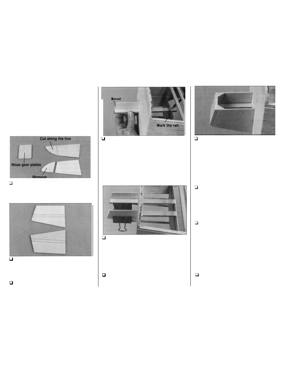
Draw a line connecting the punch marks on
both die-cut 1/8" plywood nose landing gear
braces. Cut the braces off at the line. Glue the two
die-cut 1/8" plywood nose gear plates together.
F2.
Place the braces over their location
on the
plan. Mark the location of the 1/4" plywood landing
gear rails onto the braces.
F3. Remove the engine mount from the firewall.
F4.
Cut a bevel on the end of the 1/4" x 9/16"
x
9"
plywood landing gear rails to match the angle
on the end
of the braces. Test fit a rail through the
right side of the firewall and in the notch in former
F2. Position the right brace and align the front of
the rail with the front of the brace. Mark the rail 1/8"
aft
of former F2. Remove the rail and cut it at
the mark. Mark the other rail in the same manner.
F5.
Use 30-minute epoxy to simultaneously glue
the rails to the firewall and former F2, and the rail
braces to the rails and the firewall. Make sure the
front of the rails are even with the front of
the braces.
F6.
Drill 1/8" holes through the punch marks in the
nose gear plate. Press four 4-40 blind nuts into the
holes in the plate, and secure them with thin CA.
-
52
-
F7.
Position the nose gear plate on the front of
the braces. Trim the rails
so
the blind nuts do not
interfere. Use 30-minute epoxy to glue the nose
gear plate to the rails and rail braces. Hold the
plate in position with masking tape until the epoxy
is fully cured. Add balsa triangle braces as shown
on the plan cut from leftover fuse corner stringers.
See the photo at step 11.
F8. Mount the nylon nose gear bearing to the
nose plate with four 4-40
x 1/2" screws. Enlarge
the holes in the nose gear bearing for the nose
gear strut with a #10 drill bit (if you don't have a
numbered drill set, an 11/64" drill bit will work too).
F9. Enlarge the outer hole in the black, nylon
steering arm with a # 41 drill bit or a hobby knife.
Mount the heavy duty Screw-Lock connector to
the steering arm with the one-way star washer.
Mount the 3 / 1 6 nose gear wire to the nose gear
bearing with a 3/16" wheel collar and set screw
and the steering arm and a 6-32
x 1/4" socket head
cap screws as shown on the plan. Notice that the
steering arm is slightly off center when the nose
gear is centered.
FIO. Temporarily fit your nose steering servo
and tray on the forward servo rails. Fit a servo arm
to
your servo.