Top Flite TOPA0305 Part 2 User Manual
Page 18
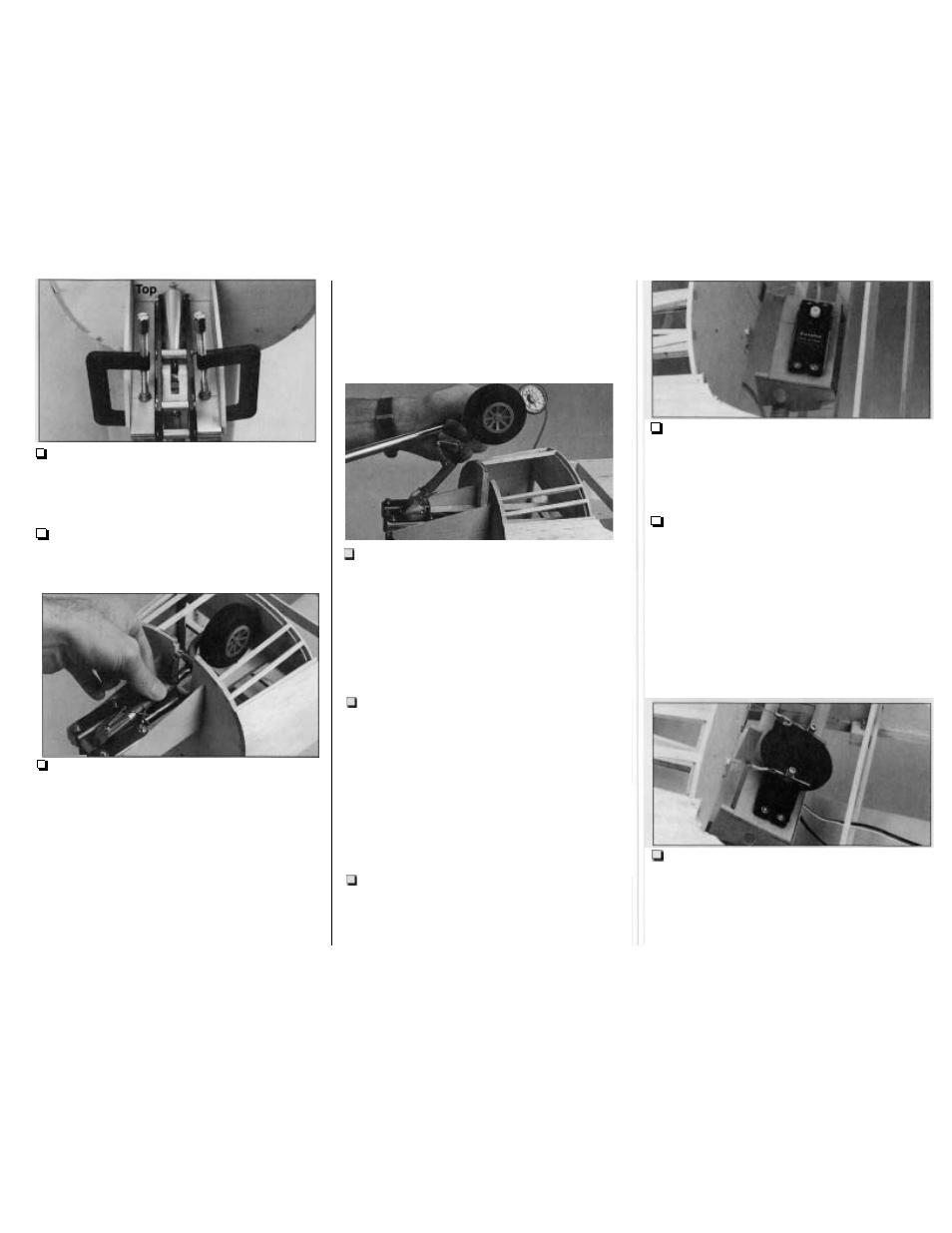
R5. Use small clamps to hold the nose gear to
the rails
so
the pivot point (on the Robart 631's)
aligns with the marks you made on the top of the
rails. Mark the locations of the mounting holes on
the landing gear rails.
R6. Remove the landing gear and drill 5/32"
holes at the marks you made. Temporarily mount
your landing gear with 6-32
x 3/4 screws and blind
nuts (not included).
R7.
Remove the two 3/16" stringers that
interfere with the wheel and strut. Use a Dremel
Tool or a razor saw to cut the firewall to
accommodate the strut. Retract the nose gear and
make sure it does not interfere with the firewall.
Note:
Adjust the
centering spring
on your retracts
so
the nose wheel is neutral and make sure the
nose wheel is centered on the strut. On the Robart
631 strut we inserted two #8 washers between the
wheel and the strut to center the wheel. The nose
wheel
must
be
neutral
and
centered
to fit
between the rails when retracted.
Hint:
File or sand a slight bevel to the bottom
edges of the rails to guide the nose wheel, in case
R8. If you have your air pump and some quick
disconnects handy, temporarily connect them to
your nose gear air cylinder and actuate the nose
gear with the air pump. This will give you a good
indication of any problem areas that you can
U
R9.
Cut 3/16" off the aft edge of the die-cut 1/8"
plywood
nose steering servo tray.
Mount your
nose steering servo to the servo tray
so
the output
shaft is on the
left
side of the servo tray as shown
on the plan. See the photo at step R11. Note that
the servo is offset toward the aft edge of the servo
u
R10.
If
you would like to mount your air control
valve in the same location as in our prototype, drill
a 1/2" hole in the die-cut 118" plywood
right nose
steering servo tray mount
at the punch mark.
R11. Test fit the servo tray (with the servo) in the
die-cut 1/8" plywood
servo tray mounts
and fit the
assembly in the servo rails. Position the mounts
and the tray
so
the output shaft of the servo is
centered between the 1/8" holes in former F2. Glue
the servo tray and the mounts in this position.
R12. Cut two 4-5/8" pieces from the white nose
steering cable inner pushrod guide tube and slide
the pieces through the holes in the firewall and
former
F2.
Glue the tubes to the firewall and F2.
CONNECT THE NOSE
Several pull-pull steering cable systems are
available that will work in your Bonanza. We
selected the Sonictronics #121 Pro-Control Cable
System.
STEERING PULL-PULL
R1. Enlarge the hole in two Screw-Lock pushrod
connectors with a #46 or 5/64" drill bit. Mount the
screw-lock connectors to a large servo arm and
fasten each with a nylon retainer. Connect one end
of a 14" long pull-pull cable to a threaded rod
included with the pull-pull steering set using the
-54-
correct now.