Top Flite TOPA0305 Part 2 User Manual
Page 15
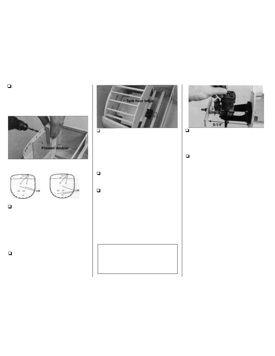
5 .
Glue the die-cut 1/8" plywood
firewall
doubler
to the back of the firewall, centered on the
engine mount punch marks, 1/8" below the notch in
the center of F1DT as shown on the plan.
FIXED LANDING GEAR
RETRACT LANDING GEAR
(VIEWED FROM THE FRONT)
IVIEWED FROM THE FRONT)
7/32"
7/32"
6. Drill the correct size holes through the punch
marks on the front of the firewall as shown in the
sketches above. Tightly hold a
thick
block of wood
on the back
so the drill does not split the wood
when it comes through.
7.
Press four 8-32 blind nuts into the holes on
the back of the firewall. Use an 8-32
x
1-1/2"
socket head cap screw with some large washers to
draw the blind nuts into the wood. Wick thin CA
around the back of the blind nuts to permanently
hold them in place.
8.
Temporarily clamp the die-cut
1/8"
plywood
tank floor
to the forward servo rail so it is centered
on the back of the firewall doubler. Turn the
fuselage over and push the tank floor up until it
contacts the edge of the bottom blind nuts. Glue a
3/16"
x
3/16"
x
3" balsa stick to the back of the
firewall under the tank floor to serve as a
forward
tank floor
ledge.
Do
not glue the tank floor to the
ledge until instructed to do so.
9. If you have not already done so, sand the
fuselage side doublers and fuselage sides
so they
are flush with the front of the firewall.
10. Cut the spacer bar off both
engine mount
halves and trim off any flashing
so they easily fit
together. Loosely bolt your engine mount to the
firewall with four 8/32
x 1-1/4" socket head cap
screws,
#8
lock washers and flat washers. Adjust
the mount so your engine will fit. Tighten the
screws to securely hold the mount to the firewall.
Use small clamps
to
hold your engine to the mount
so the front of the drive washer (or the back plate
of your spinner) is 6-1/4 from the firewall. Mount a
flat wood stick or the back plate of your spinner to
the engine so you can measure the distance.
Beech Fact: In addition to the aforementioned
benefits the V-tail offers, others include lower
manufacturing costs through fewer parts, fewer parts
for Beech dealers to stock, reduced damage from
debris thrown from the prop and wheels, and spin
recovery superior to that of an airplane with a
conventional tail.
11. Mark the engine mounting bolt holes on the
mount.
Hint:
Mark the holes with a wire rod
sharpened at one end. Heat the tip of the rod with a
torch to dimple the engine mount in the
center
of
the holes.
12. Remove the engine from the mount and the
mount from the firewall. Use a drill press,
if you
have access to one, or use a hand drill to drill the
holes with a #29 or 9 / 6 4 drill bit for 8-32 screws.
Tap 8-32 threads into the mount. Screw the mount
back onto the firewall. Screw the engine to the
mount with 8-32
x
1" screws to see how it fits.
- 5 1
-