Top Flite TOPA0305 Part 2 User Manual
Page 14
FIT THE TAIL CONE
ST1. Glue the die-cut 1/8" balsa t a i l c o n e
f o r m e r (F11TC) on the end of the fuselage.
Remove material as needed to clear the torque
rods and pushrods. There must be
no possibility
of binding here.
ST2. Refer to the photo at step V2 on page
44.
It
shows the V-tail but the straight tail is the same.
Glue the die-cut 1/8" plywood tail cone mounts to
the tail cone former. Cut round notches in the tail
cone to clear the joiner wire. Fit the tail cone on the
aft end of the fuse and fasten it to the mounts with
four
#2
x
3/8" screws. Make sure the screws
do
not
interfere with the elevator torque rod.
ST3. Remove the elevators and joiner wire.
Mount the tail cone to the fuselage.
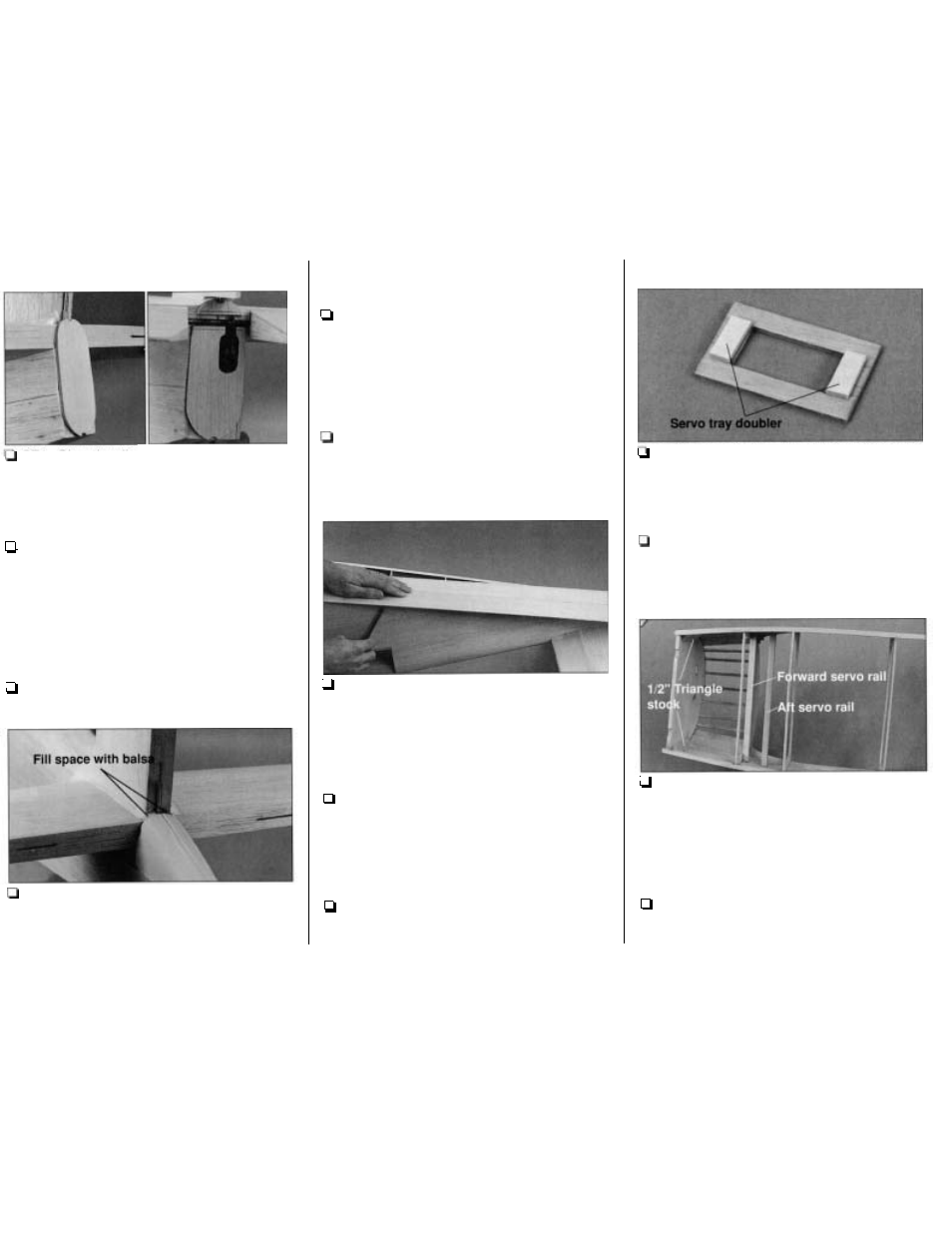
ST4.
Fill
the small space between the top of the
tail cone and the TE of the rudder with leftover
balsa. Use lightweight hobby filler to blend the fin to
the stab and the tail cone to the fin.
SHEET THE BOTTOM OF THE
FUSELAGE
1. If you are going to hook up working lights,
now is a convenient time to route the wire for the
light in the tail. Route the wire through the formers.
Glue the wire to the formers with rubber cement or
a drop of CA
so they don't rattle around. Allow
enough wire to extend past former F11
so it will
extend about 2" past the back of the tail cone.
2. Cut a
3/32"
x 3" x 30" balsa sheet to a length
of 2 8 . True both edges of the sheet with a hobby
knife and a straightedge. Pin the sheet to the
bottom of the fuselage in the 'center
so the end
butts against the front edge of the tail cone.
3. True both edges of another 3/32" x 3" x 30"
balsa sheet. Position the sheet on the bottom of the
fuselage next to the center sheet. Use a ballpoint
pen to mark the side of the fuselage onto the sheet.
Cut the sheet along the line you drew. Do the same
with the remainder of the sheet on the other side of
the fuselage.
4.
Glue the three bottom sheets together. After
the glue dries, sand the fuselage bottom sheet
so it
is flat and the edges are even. Sand the bottom at
the formers and stringers
so that they are even and
flat. Glue the fuselage bottom sheet to the bottom
of the fuselage.
5. Shape the bottom corners of the fuselage as
shown in the cross sections on the plan
so they
blend with the tail cone at the rear.
-
50
-
MOUNT THE ENGINE
1.
Glue the die-cut 1/8" plywood servo tray
d o u b l e r s to the bottom of both die-cut 118"
plywood forward servo trays. Mount your throttle
servo to one tray and your nose wheel steering
servo to the other tray.
2. Cut a 8-3/4" forward
servo
rail from a
1/4"
x
3/8" x 36" basswood stick to fit between the
fuselage sides behind former F2. Test fit, then glue
the servo rail to the fuse sides and former F2 1-7/8"
below the top edge
of F2.
3. Cut a 8-13/16"
aft
servo rail
to
fit between
the fuselage side doublers
7/8"
aft of the forward
servo rail. Place the throttle and nose wheel
steering servo and tray between the rails. Adjust
the position of the aft rail to fit your servos. Glue
the aft servo rail in place. Do not glue the servo
trays in place until instructed to do
so.
4.
Glue the F l T / F l DT assembly to the top of the
firewall. Use a straightedge to make sure
they align.