Toa S-D7802 User Manual
Page 9
9
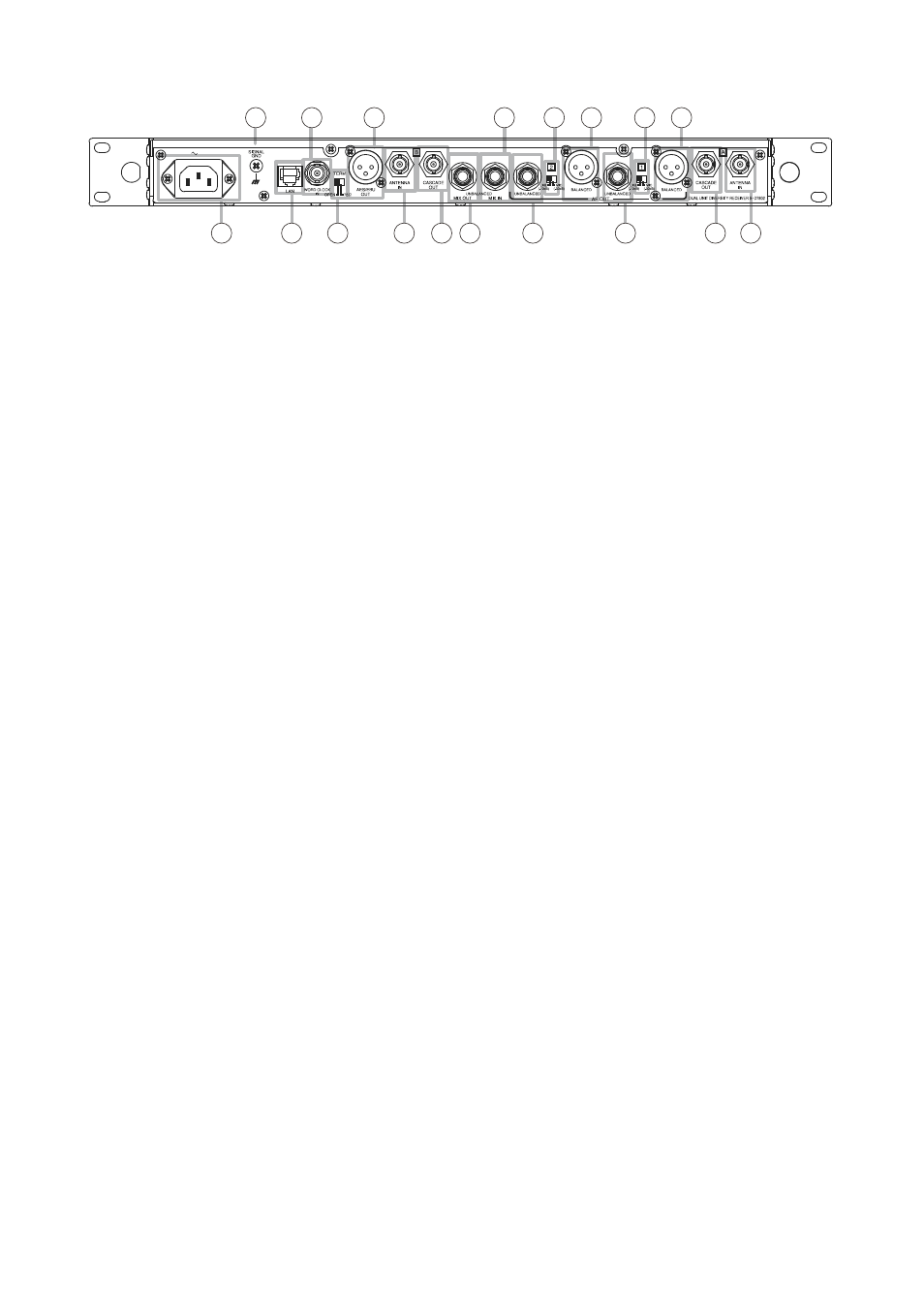
[Rear Panel]
22. Functional earth terminal
To ensure stable operation, be sure to ground this
terminal.
Note
This terminal is not for protective earth.
23. word clock input terminal [wORD ClOCK IN]
Allows connection to a word clock signal source.
24. AES/EBU output connector
XLR-3-32 or equivalent connector (Pin No. 1:
Ground, Pin Nos. 2 and 3: Signal),
AES/EBU Digital output connector. Outputs digital
audio signals to an AES/EBU input-equipped
device.
Note
For connection, use the XLR-3-11C or equivalent
connector and the digital audio cable with
characteristic impedance of 110 Ω.
25. mixing input jack
Phone jack, –10 dB*, unbalanced (at reference
output).
Audio signals from the mixing input, Unit 1, and
Unit 2 are all mixed and sent to the Mixing output
jack (35).
26. Unit 2 audio output level selector switch
Switches Unit 2's audio output level.
"MIC" position: –30 dB*
"Line" position: –10 dB* (at reference output)
27. Unit 2 audio output xlR (balanced)
XLR-3-32 or equivalent connector.
Balanced independent audio output of the Unit 2.
Electronically-balanced output terminal (Pin No.
1: Ground, Pin No. 2: Hot, Pin No. 3: Cold).
Connect to the microphone input terminal or
line input terminal of the connected device.
(Use the XLR-3-11C or equivalent connector for
connection.)
28. Unit 1 audio output level selector switch
Switches Unit 1's audio output level.
"MIC" position: –30 dB*
"Line" position: –10 dB* (at reference output)
29. Unit 1 audio output xlR (balanced)
XLR-3-32 or equivalent connector.
Balanced independent audio output of the Unit 1.
Electronically-balanced output terminal (Pin No.
1: Ground, Pin No. 2: Hot, Pin No. 3: Cold)
Connect to the microphone input terminal or
line input terminal of the connected device.
(Use the XLR-3-11C or equivalent connector for
connection.)
30. AC inlet
100 - 240 V AC, 50/60 Hz.
Used to connect an accessory AC Power Cord
(2 m).
31. lAN connector [lAN]
Used to connect to a PC via an Ethernet cable.
Ready for 10BASE-T or 100BASE-T.
For more information, see p. 27, "Network
32. Terminal selector switch [TERm]
Sets the word clock termination to "Open" or "75 Ω."
33. B antenna input connector
BNC jack.
Connects to a wireless antenna.
Supplies DC power to the antenna. (9 V DC, Max.
90 mA)
Up to 2 YW-7000 Antenna boosters (optional) can
be connected to the antenna input jack.
Note
Never connect a termination resistor to the idle
antenna input connector. Doing so short-circuits
the supply power to the antenna.
34. B antenna cascade output connector
BNC jack.
Connect to the second S-D7802 Diversity wireless
receiver's B antenna input jack.
Tip
You do not need to connect the termination
resistor to the idle antenna connector.
For more information, see p. 17, "Sharing an
* 0 dB = 0.775 V
22
23
24
25
26 27
28 29
30
31
32
33 34 35
36
37
38 39
100 – 240V 500mA 50/60Hz