Speaker wiring -7, 1 wiring procedure -7, 4 speaker wiring – SilentKnight SKE-450 Voice Evacuation Control Panel User Manual
Page 51: 1 wiring procedure
SKE-ZN6 Six Zone Splitter Installation
151267
6-7
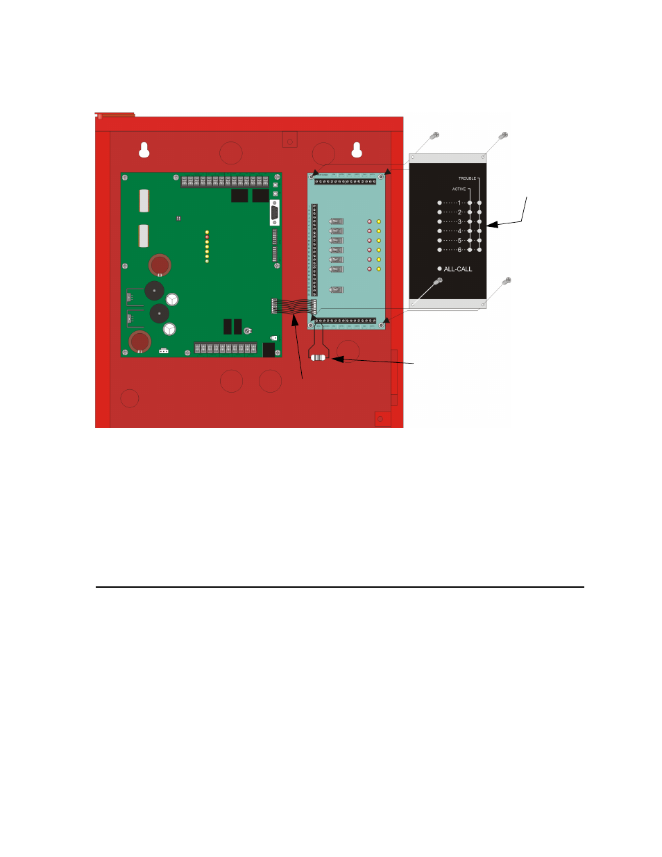
6. Connect wiring harness to the expansion connector on the SKE450 and to the direct
connect pins on the SKE-ZN6. See Figure 6-4.
Figure 6-4 View With SKE-ZN6 Installed
7. Wire speaker to zone outputs as required by the installation specifications. Refer to
8. Attach the SKE-ZN6 cover plate to the SKE-ZN6. See Figure 6-4.
Note: Speaker outputs of the SKE-450 must not be used when using the SKE-ZN6 because supervision will not be
provided at the SKE-450.
6.4 Speaker Wiring
Each SKE-ZN6 supplies six NACs (Notification Appliance Circuits) for speaker connection.
The speaker circuits can be supervised and wired Class B (Style Y) or Class A (Style Z). Each
speaker circuit is capable of 20 watts of power.
Note:
This configuration illustrates a 25V installation if using an SKE-V70. For 70.7V installations, see Sec-
tion Section 8.
6.4.1
Wiring Procedure
In order to gain access to the terminals on the SKE-ZN6, the cover plate must be removed.
See Figure 6-4.
15 k
Ω EOL
UL Listed
Model 7630
Wiring Harness (P/N 130427)
SKE-ZN6
Cover Plate