Warning – Reznor R6GP Unit Installation Manual User Manual
Page 8
8
Air Filter Requirements
WARNING:
Never operate the unit without a filter in place.
Dust and lint could accumulate on internal
parts, resulting in loss of efficiency, equipment
damage and possible fire.
All return air must pass through the filters before entering
the unit. It is important that all filters be kept clean and
replaced frequently to ensure proper operation of unit.
Dirty or clogged filters will reduce the efficiency of the
unit and result in unit shutdowns. Air filter pressure drop
must not exceed 0.08 inches WC. When replacing the air
filters, a suitable air filter must be installed ahead of the
evaporator coil of the return air system. Refer to Table 1
for recommended filter sizes.
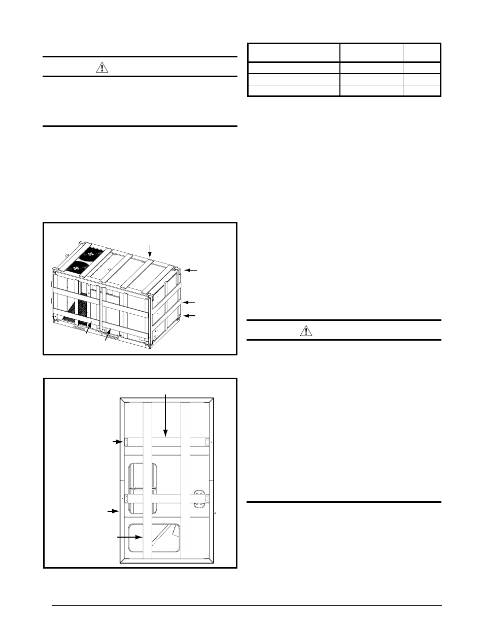
Figure 3. Bottom View
Crate Brackets (x4)
Long Bottom
Boards (x2)
Short Bottom
Boards (x2)
Base
Rails
Figure 2. Side View
Wood Cap
Assembly
Top Crate
Brackets
Lower
Crate
Brackets
End Skid
Side Skids
UNIT
FACTORY
FILTER SIZE
QTY
R6GP-072*-(100/166)C
16x20x2
4
R6GP-090*-200C
16x20x2
4
R6GP-120*-235C
16x25x2
4
Table 1. Filter Sizes & Quantities
UNIT INSTALLATION
Packaging Removal
All units have been securely packaged at the point of
shipment. After unpacking the unit, carefully inspect for
apparent and concealed damage. Claims for damage
should be filed with the carrier by the consignee.
1. Remove top crate brackets and wooden cap assembly
from top of unit (Figure 2).
2. Remove lower crate brackets, 4 side skids, and 2 end
skids from each side of unit. NOTE: DO NOT remove
base rails from unit.
3. Rig unit and raise up approximately 4 feet off the ground.
4. Remove crate brackets (Figure 3) securing long and
short bottom boards to underside of unit. NOTE: Some
screws are located in fork slots.
5. Remove long & short bottom boards from beneath unit.
6. Inspect unit thoroughly for shipping damage.
7. Carefully lower and position unit to it’s permanent
location.
Rigging & Hoisting
WARNING:
To avoid the risk of property damage, personal
injury, or death, it is the rigger’s responsibility
to ensure that whatever means are used to hoist
the unit are safe and adequate:
• The lifting equipment must be adequate for the
load. Refer to Table 3 (page 27) for unit weights.
• The unit must be lifted from the holes in the
base rails using cables or chains.
• Spreader bars are required to protect the unit
and ensure even loading. See Figure 4.
• Keep the unit in an upright position at all times.
The rigging must be located outside the units
center of gravity. Refer to Figures 12 - 14 (pages
22 - 27) for locating the center of gravity.
• All panels must be securely in place during
rigging and hoisting.
Minimum Clearance Requirements
R6GP units are certified as combination heating and
cooling equipment for outdoor installation only. Figure 5
(page 9) displays the minimum clearances to combustible
materials for both Downflow and Horizontal discharge.
R6GP units may be installed on non-combustible surfaces
when used with bottom supply and return air ducts.
Units may be installed on wood flooring or on Class A,