Unbalanced 3-phase supply voltage, Thermostat / low voltage connections, Heat anticipator – Reznor R6GP Unit Installation Manual User Manual
Page 14: Blower speed
14
Example
:
AB = 451V
BC = 460V
AC = 453V
2. Determine the average voltage in the power supply.
3. Determine the maximum deviation:
4. Determine percent of voltage
imbalance by using the results
from steps 2 & 3 in the following
equation.
max voltage deviation
from average voltage
= 100 x
average voltage
% Voltage Imbalance
6
454
100 x
= 1.32%
Example:
1. Measure the line voltages
of your 3-phase power
supply where it enters the
building and at a location
that will only be dedicated
to the unit installation (at
the units circuit protection
or disconnect).
Unbalanced 3-Phase Supply Voltage
Voltage unbalance occurs when the voltages of all phases
of a 3-phase power supply are no longer equal. This
unbalance reduces motor efficiency and performance.
Some underlying causes of voltage unbalance may include:
Lack of symmetry in transmission lines, large single-phase
loads, and unbalanced or overloaded transformers. A
motor should never be operated when a phase imbalance
in supply is greater than 2%. Perform the following steps
to determine the percentage of voltage imbalance:
In this example, the measured line voltages were
451, 460, and 453. The average would be 454 volts
(451 + 460 + 453 = 1,364 / 3 = 454).
The amount of phase imbalance (1.32%) is satisfactory
since the amount is lower than the maximum allowable
2%. Please contact your local electric utility company if
your voltage imbalance is more than 2%.
Example:
From the values given in step 1, the BC voltage (460V)
is the greatest difference in value from the average:
460 - 454 = 6
454 - 451 = 3
454 - 453 = 1
Highest Value
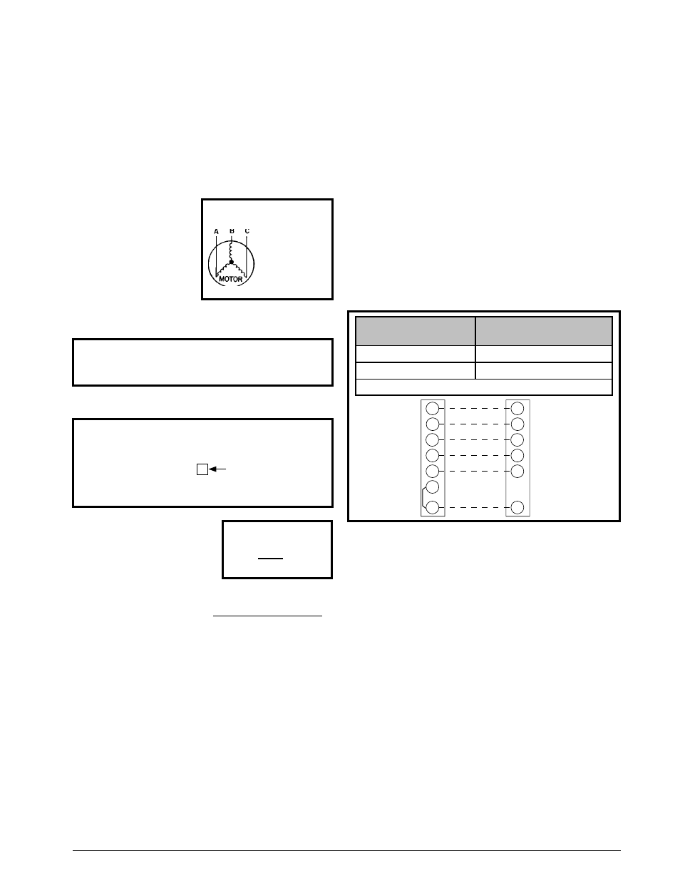
Figure 10. Typical 2 - Stage Heat/Cool
Thermostat Connection
Y1
Y2
W2
W1
G
RH
RC
Y1
Y2
W2
W1
G
R
Indoor
Thermostat
Sub-Base
Unit Low Voltage
Terminal
T-Stat Wire
Gauge
Recommended T-Stat Wire
Length - Ft. (Unit to T-Stat)
18 Ga.
0 - 60
16 Ga.
61 - 130
Field Supplied Wiring - - - - - Use Solid Class II Copper Wire
• A two-stage heating/cooling thermostat is required for
R6GP series units. Select a thermostat which operates
in conjunction with the installed accessories. See Figure
10 for proper wire gauge and their recommended lengths
for typical thermostat connections.
• The low voltage wires must be properly connected
to the units low voltage terminal block. Route 24V
control wires through the gas furnace side of the unit.
Recommended wire gauge and wire lengths for typical
thermostat connections are shown in Figure 10.
• The thermostat should be mounted about 5 feet above
the floor on an inside wall. DO NOT install the thermostat
on an outside wall or any other location where its
operation may be adversely affected by radiant heat from
fireplaces, sunlight, or lighting fixtures, and convective
heat from warm air registers or electrical appliances.
Refer to the thermostat manufacturer’s instruction sheet
for detailed mounting information.
Thermostat / Low Voltage Connections
• Single Package Gas Heating / Electric Cooling Rooftop
Units are designed to operate with a 24 VAC Class II
control circuit. The control circuit wiring must comply
with the current provisions of the NEC (ANSI/NFPA
70) and with applicable local codes having jurisdiction.
Thermostat connections should be made in accordance
with the instructions supplied with the thermostat.
Heat Anticipator
Verify if the thermostat being used for the installation has a
heat anticipator setting. This function allows the thermostat
to anticipate the space heating rate and time the burner
to shutoff accordingly. Always refer to the thermostat
manufacturers instructions for the correct settings.
Blower Speed
The blower speed is preset at the factory but must
be verified at each installation. For optimum system
performance and comfort, it may be necessary to change
the factory set speed. Refer to Blower Performance Data
(Tables 5 - 12, pages 29 - 36) for proper operating range.
Always ensure drive belt is secure and tensioned properly.
Also inspect variable pitch sheaves for proper tightness
of the set screws