Warning – Reznor R6GP Unit Installation Manual User Manual
Page 6
6
COMBUSTION AIR & VENTING
WARNING:
Installation methods other than those described
in the following sections must comply with the
National Fuel Gas Code and all applicable local
codes for providing sufficient combustion air
to the furnace.
Provisions must be made during the installation of this
unit that provide an adequate supply of air for combustion.
• Instructions for determining the adequacy of an
installation can be found in the current revision of the
NFGC (ANSI Z223.1 / NFPA54).
Consult local codes
for special requirements
. These requirements are for
US installations as found in the NFGC.
• The requirements in Canada (B149.1) are structured
differently. Consult with B149.1 and local code officials
for Canadian installations.
WARNING:
Combustion air must not be drawn from a
contaminated atmosphere. Excessive exposure
to contaminated combustion air will result in
safety and performance related problems.
To maximize heat exchanger life, the combustion air
must be free of chemicals that can form corrosive acidic
compounds in the combustion gases. The recommended
source of combustion air is to use clean air from outside.
DO NOT place any chemicals with flammable or caustic
vapors or these other corrosive chemicals near the
vent termination:
• Gasoline/Kerosene
• Permanent wave solutions
• Chlorinated waxes and cleaners
• Chlorine based swimming pool chemicals
• Water softening chemicals
• De-icing salts or chemicals
• Carbon tetrachloride
• Halogen type refrigerants
• Cleaning solvents
• Cements, glues, paint removers, varnishes, etc.
• Hydrochloric acid
• Masonry acid washing materials
• Plumbing Stack
Air openings in the door of the unit, warm air registers, and
return air grilles must never be restricted. If the unit does
not receive an adequate supply of air for combustion, the
flame roll-out control located above the burners will open,
turning off the gas supply to the burners. This safety device
is a manually reset switch. IMPORTANT NOTE: DO NOT
install jumper wires across this control to defeat its
function or reset the control without identifying and
correcting the fault condition.
If this control must be replaced, use only factory authorized
replacement parts specified in the Replacement Parts
List provided online.
Vent Termination
This unit has been equipped with an integral venting
system and designed to operate only with this venting
system. If desired, an accessory venting kit is available.
Use only NORDYNE approved venting kit listed in the
technical service literature
.
WARNING:
This unit is intended for outdoor installation
only. Do not vent the unit through a conventional
venting system.
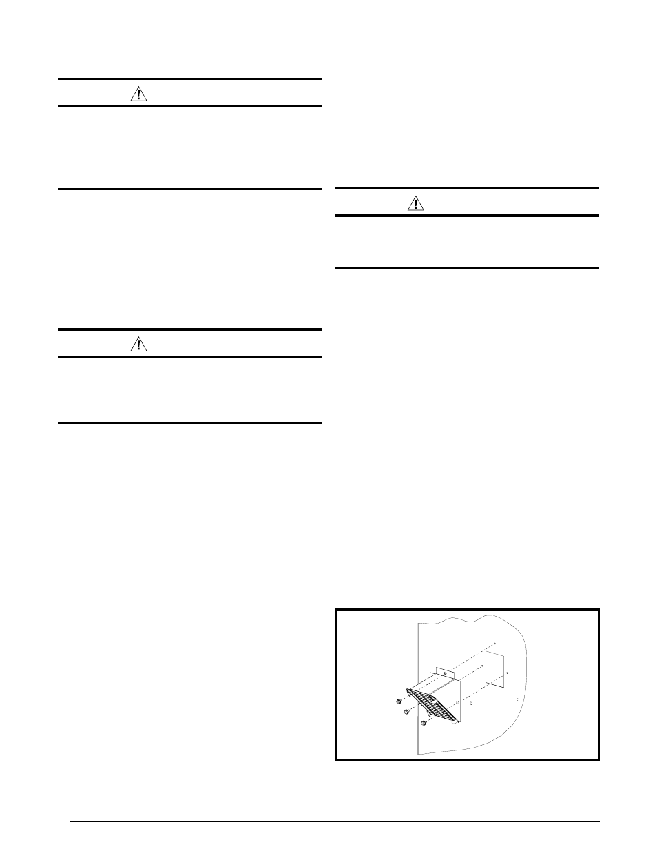
A vent cover assembly has been supplied with the unit
and can be found secured to the gas controls within the
burner area of this unit.
Figure 1 displays the proper
installation of the vent cover assembly over the vent outlet
of the corner panel. The fasteners used to secure the vent
cover assembly have been included on the unit end panel.
The list below summarizes the location requirements for
the venting system termination:
• The location of the vent termination must be consistent
with the National Fuel Gas Code (ANSI Z223.1) or CAN/
CGA-B149 Installation Codes.
• Must be located at least 4 feet horizontally from any
electric meters, gas meters, regulators, and relief
equipment.
• Must be located at least 3 feet above any forced air inlet
located within 10 feet of unit.
• Must be located at least 4 feet below, 4 feet horizontally
from, or 1 foot above any door, window, or gravity air
inlet into any building.
• Must be located at least 1 foot above grade and installed
in such a manner as to prevent snow accumulation from
obstructing the vent termination.
• The vent termination must not be located above any
public walkways.
• The vent cover assembly must be installed to assure
proper operation of the unit.
Figure 1. Vent Cover Assembly