Wiring dia gram, 3 phase 60 hz, R6gp series 6-10t – Reznor R6GP Unit Installation Manual User Manual
Page 38
38
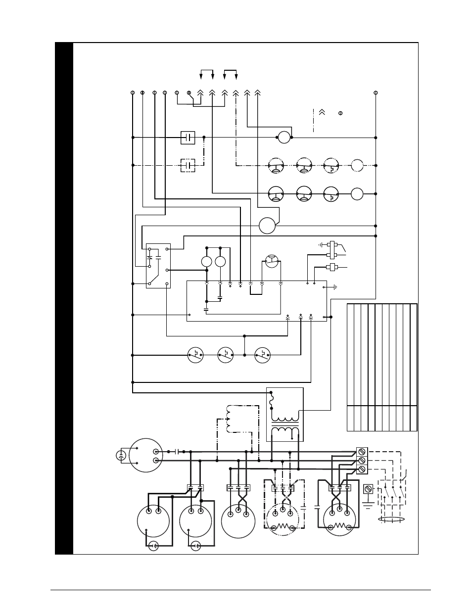
Figure 15. Ladder Diagram - 072 / 090 / 120 Series
3 Phase 60 Hz.
4.
For suppl
y wire ampacities and o
ver
current pr
otection
,
see unit
rating label.
5.
On
“C”
Series Models on
ly
.
For 208V operation remo
ve wire fr
om
230V tap and place on 208V tap.
6.
This wire replaced
by
auto transf
ormer when used.
1.
Couper le courant
av
ant de faire letretien.
2.
Empl
oy
ez uniquement des conducteu
rs
en cuivre
.
WIRING DIA
GRAM
R6GP Series 6-10T
NO
TES:
1.
Disconnect all po
wer bef
ore servicing.
2.
For suppl
y connections use copper conductor
s on
ly
.
3.
If an
y of the original wire as supplied with the furnace m
ust be replaced,
it m
ust be replaced with wiring material ha
ving a temperature rating of
at least 105C.
CCH - Crankcase Heaters
, Stage 1&2 Compressor
CC1&2 - Contactor
, Stage 1&2 Compressor
E - Economi
ze
r
LVT - Lo
w
V
oltage
Te
rm
inal
OFC - Contacto
r,
Outdoor
Fa
n
IBC - Contactor
, Indoor Blo
wer Motor
L1
L2
L3
GND
Compressor 1
T2
T1
T3
CC1
Au
x.
Switch (N.C
.)
CC1
CCH1
Field Supplied
Disconnect
(3Phase
Po
wer Only)
Fo
r supply connections use
copper conductors only
.
Unit
Te
rminal
Bloc
k
24V
Ho
t
High
Pressure
Switchs
Ev
ap
.
F
reez
estats
Lo
w
Pressure
Switchs
Y1
F
actor
y
J
umper
LV
T
-C (24V COM.)
LV
T-
R
CC1
LV
T-
Y1(Stage 1 Cool)
LV
T-
Y2(Stage 2 Cool)
LV
T-
G
LV
T-
W1(Heat)
LV
T-
W2(Heat)
E-1
E-9
E-8
E-2
E-4
E-5
OFC
CC1
A
ux.
Switch
(N.O
.)
CC2
A
ux.
Switch
(N.O
.)
Y2
F
actor
y
J
umper
WH
BK
Inducer Motor
208-230/460
V
olt
1
3
Max
Te
mp
.
Limit
24V Common
Flame
Rollout
Switch
Upper
Scndr
y
Limit
P1-2
P1-8
P1-3
P2-3
K2
S1
S2
UTEC
IGNITION
CONTR
OL
G
C
R
L
COM
NC
NO
BLO
WER
TIME
DELA
Y
K1
P2-4
W1
W2
HV
TRANSFORMER
FS
P2-1
COM
P1-9
P1-6
GAS
VA
LV
E
INDUCER MTR
CENTRIFUGAL
SWITCH
SP
ARK
IGNIT
OR
FLAME
SENSOR
GND
High
Limit
Input
Rollout Switch
Input
C
IBC
T2
T3
T1
IBC
Tr
ansf
or
mer
24V Sec.
Primar
y
Indoor
Fa
n Motor
See Note 5
OFC
4 Amp
Circuit
Brea
ke
r
Au
to
Tr
ansf
or
mer
460V Units Only
L3
L2
See Note 6
P1-7
P1-4
24
VA
C
P2-2
R
IC-IND
K4-IC
IC-L1
Status Light
(Red)
Ignition Control F
ailure Code
Steady On
2 flashes
Operation No
rm
al
3 flashes
4 flashes
5 flashes
6 flashes
7 flashes
8 flashes
9 flashes
10 flashes
Pressure/centr
ifugal s
witch open with inducer on
Loc
ko
ut from too ma
ny
f
ailed ignition tr
ies
Loc
ko
ut from too ma
ny
flame losses
High temperature
sw
itch open
Rollout
sw
itch open
Flame present with gas off`
Exceeded max limit tr
ips in one call
fo
r heat (5)
Gas
Va
lv
e
Fa
ult
Pressure/centr
ifugal s
witch closed with inducer off
R
C
Outdoor F
an Motor
Outdoor F
an Motor
S
R
C
S
See Alter
nate
OD f
an wi
ri
ng
Diagram
B
T2
T3
T1
CC2
Compressor 2
Au
x.
Switch
(N.C
.)
CC2
CCH2
711153A
04/11
(Replaces 7111530)
- Indicates plug connection.
Letter Indicates which plug.
Number indicates pin location.
2 Stage Equipment Only
- Indicates scre
w connection.
CC2