Troubleshooting, Table 2. diagnostic codes for 6 - 10 ton units, Figure 11. location of unit components – Reznor R6GP Unit Installation Manual User Manual
Page 21
21
If the unit does not operate properly in the cooling mode,
check the following:
• The thermostat is operating properly.
• Electrical power to the unit is turned on.
• All safety switches are closed.
• The service doors are in place.
• Transformer circuit breaker is reset.
If the unit does not operate properly in the heating mode,
check the following:
• The thermostat is operating properly.
• Electrical power to the unit is turned on.
• All safety switches are closed.
• The gas is on and shut-off valve is open.
• The service doors are in place.
• The flame roll-out control is closed.
• Refer to the diagnostic codes in Table 2 or the wiring
diagram (Figure 15, page 38).
• Transformer circuit breaker is reset.
STATUS LIGHT
(Red LED)
FAULT
CONDITION
Continuous ON
Operation Normal
2 Flashes
Pressure / centrifugal switch open with
inducer on
3 Flashes
Pressure / centrifugal switch closed with
inducer off
4 Flashes
Lockout from too many failed ignition tries
5 Flashes
Lockout from too many flame losses
6 Flashes
High temperature switch open
7 Flashes
Rollout switch open
8 Flashes
Flame present with gas off
9 Flashes
Exceeded max limit trips (5) in one call for
heat
10 Flashes
Gas valve fault
Table 2. Diagnostic Codes For 6 - 10 Ton Units
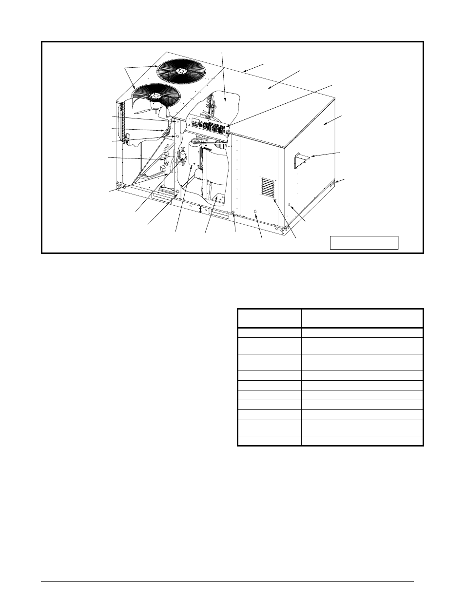
Condenser Fan
Assemblies
High/Low
Pressure Switch
Protection
Liquid Line
Filter Driers
High Efficiency
Compressors
with Crankcase
Heaters
Belt Drive
Blower Motor
Knockout
for Bottom
Power Entry**
3/4” PVC
Condensate
Drain
Permament Baserail -
No Need for Removal
with Roof Curb
Knockout for
Bottom Power
Entry
Control Wiring Entry
Power Wiring Entry
Condenser Coils
Electrical
Disconnect
Mounting
Panel +
Easy Access
Control Panel
Durable Pre-Coat
Paint
Quick Release
Filter Panel
Evaporator Coils
Exhaust Vent
Gas Line Inlet
Flame
Observation
Combustion
Air Inlet
+ Field Supplied
** Field Installed Kit Required
Figure 11. Location of Unit Components
Model R6GP-120C235C Shown
TROUBLESHOOTING