Notice, Fuel system – step 5 – Proheat X45–School Bus User Manual
Page 69
PROHEAT INSTALLATION & SERVICE
5-12
NOTICE
Fuel Nozzle parts are a matched set
and not interchangeable.
NOTICE
DO NOT use a tip cleaner in the fuel
orifice
Fuel System – Step 5
Check:
Nozzle
a)
For fuel nozzle and o-ring damage and/or contamination.
Test Procedure — Fuel Nozzle Removal, Inspection & cleaning or replacement:
a)
Remove three (3) bolts from the fan end and open up heater.
b)
Remove nozzle from fan end.
c)
Disassemble, inspect, clean and reassemble Fuel Nozzle
(Figure 5-12).
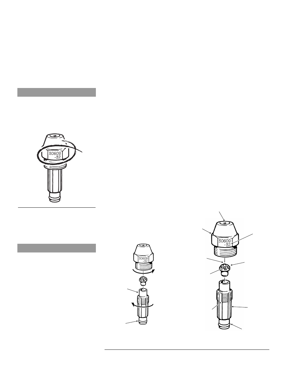
Fuel Nozzle disassembly, inspection, cleaning & reassembly:
• Hold the Fuel Nozzle stem lightly but firmly in a vise using
soft jaws, take care not to cause damage. Disassembles
in three pieces.
• Inspect Fuel Nozzle stem and O-ring for contamination and/or
damage. Inspect and clean distributor fuel orifice (a soft
bristled brush may be used), air passages, head and stem
with electrical contact cleaner or warm soapy water.
• Re-clamp the Fuel Nozzle stem lightly but firmly in a vise
using soft jaws, take care not to cause damage. Reinstall
the distributor and Fuel Nozzle head. Ensure that the
distributor is seated correctly. The Fuel Nozzle assembly is
self-aligning. Torque to 30±3 in/lbs (3.4±0.3 Nm).
d) Inspect the Fuel Nozzle cavity and clean as necessary using
electrical contact cleaner or warm soapy water
e) Reinstall Fuel Nozzle into the fan end using diesel fuel to
lubricate the o-ring. Torque to 150±10 in/lbs (17±1.1 Nm).
f)
Reinstall fan end and torque three (3) bolts to 75±5 in/lbs
(8.5±0.5 Nm)
Figure 5-11. Nozzle Number Location
FUEL NOZZLE
ORIFICE
AIR PASSAGES
AIR PASSAGES
FUEL AND AIR OUTLET ORIFICE
HEAD
DISTRIBUTOR
STEM
O-RING
NOZZLE
NUMBER
TORQUE = SEE
SECTION 1.3
LUBRICATE
O-RING WITH
DIESEL FUEL
HOLD UPRIGHT
TO ASSEMBLE
ARROWS
SHOW HOW TO
LOOSEN THE
NOZZLE
Figure 5-12
Fuel Nozzle Assembly