On/off switch connections, Caution, Notice – Proheat X45–School Bus User Manual
Page 34
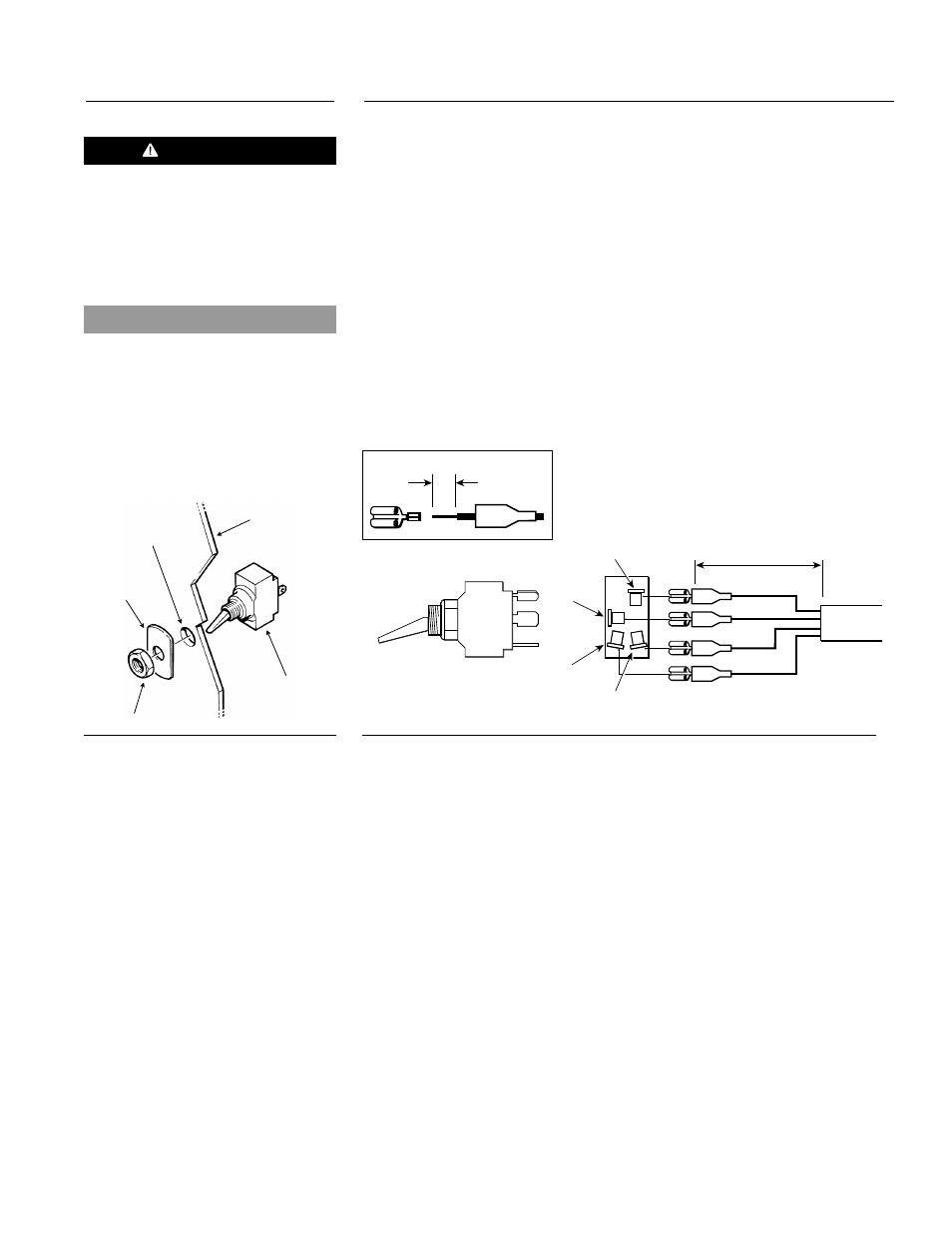
Figure 3-22
ON/OFF Switch Connections
BLACK
RED
WHITE
GREEN
GROUND
ON SIGNAL
ON
OFF
POWER
INDICATOR
2" (51 mm)
3/16"
(5 mm)
6.
Connect the terminals to the switch as shown. (Figure 3-22)
NOTE: The PCM must be reset (power disconnected and reconnected) when
changing from a Timer to an ON/OFF Switch or from an ON/OFF Switch
to a Timer. Connecting an ON/OFF Switch and a Timer in the same
circuit will cause the indicator light to flash incorrectly.
ON/OFF SWITCH CONNECTIONS
1.
Select a suitable location in the vehicle dash for the ON/OFF Switch.
NOTE: Many dash panels have switches which are not utilized. It may be
convenient to remove one and replace it with the PROHEAT switch.
2.
Drill a
1
⁄
2
" diameter hole through the dash for the switch. Make sure you
have clearance behind the dash for the switch wires and connections.
Install the switch as per the diagram. (Figure 3-21)
3.
Route the switch wire harness from the PCM to the dash panel. You will
have to pass the wire harness through the vehicle firewall. If possible use
an existing hole. Use a grommet to prevent the wire from being damaged
when it is passed through the hole.
4.
Cut the harness to length.
5.
Strip outer wire jacket of harness back to expose the 4 wires. Strip the
wires as shown and crimp the supplied
1
⁄
4
" spade terminals.
NOTE: Use fully insulated disconnects when connecting Switch.
Figure 3-21
ON/OFF Switch Assembly
DASH
NUT
ON/OFF
SWITCH
SWITCH
LABEL
1/2" DIA.
HOLE
CAUTION
The switch input circuit should only
be used to supply power to the
ON/OFF Switch, the Timer, or as a
signal to trip a relay. Failure to
follow this installation practice will
result in damage to the PCM.
NOTICE
The PCM must be reset (power
disconnected and reconnected)
when changing from a Timer to an
ON/OFF Switch or from an ON/OFF
Switch to a Timer.
Do not connect an ON/OFF Switch
and a Timer in the same circuit.
3-13
SECTION 3. INSTALLATION
3.5.4