Notice – Proheat X45–School Bus User Manual
Page 60
SECTION 5. TROUBLESHOOTING & REPAIR
5-3
The microprocessor in the PCM continually monitors all the PROHEAT
systems. If the internal diagnostics discover a problem, a diagnostic code will
be displayed on the PCM function display. The remote ON/OFF Switch, Timer
red manual light or OEM indicator light (installation options) will also flash the
diagnostic code followed by a pause and then repeat. The number of flashes
correspond to the numbered diagnostic code. For example, 5 flashes
indicates a VOLTAGE ERROR. (See diagram below for a complete list of
operation states and error flash codes.)
If multiple errors occur, multiple codes will be displayed. For example, if a 5
and 9 error occurs together, the PCM LED will flash 5 and then 9. Similarly,
the remote ON/OFF Switch, Timer red manual light or OEM indicator light
(installation options) will flash 5 times, pause and then 9 times.
OPERATION INDICATORS,
FUNCTION AND COMPONENT
DIAGNOSTICS
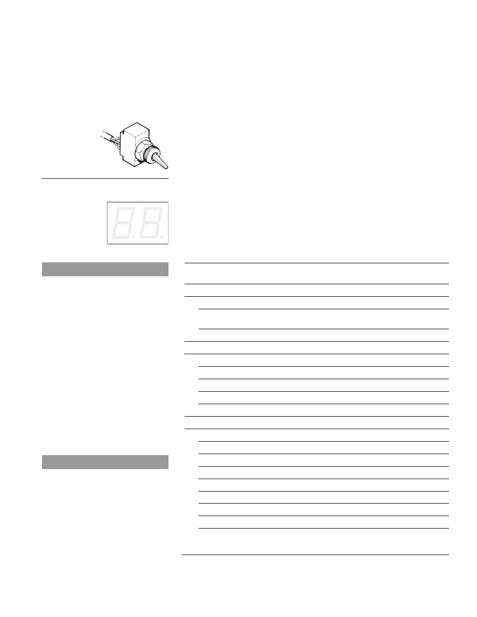
Figure 5-3
Function Display Panel Detail & Error Flash Codes
CODE No.
Description of Operating State
No. of
and Diagnostic Codes
Flashes
Operation Indicators
8.8.
Power Up
No Indicator
•
Switch On (Standard, Preheat
Solid Indicator
or Supplemental Mode)
Pu
Cool Down (Purge)
Solid Indicator
Function Diagnostics
01
Start
1
02
Flame Out
2
03
Coolant Flow
3
04
Overheat
4
05
Voltage
5
Component Diagnostics
06
Flame Sensor
6
07
Temp Sensor
7
08
Fuel Pump (See Note)
8
09
Compressor
9
10
Ignition Coil
10
11
Coolant Pump
11
12
Blower
12
13
Sleeper Fan
13
14
Hour Meter (Auxiliary Output)
14
NOTICE
The X45 fuel pump is a gear pump
driven directly by the compressor
motor. The fuel pump is NOT being
monitored electrically. Should this
component diagnostic code appear
there will be a fault in the main wire
harness connector (See page 5-35,
Figure 5-27) or in the PCM. All
mechanical problems with the fuel
pump will be indicated as either a
START (1) or a FLAME OUT (2)
diagnostic code.
NOTICE
Code 13, Sleeper Fan, is only
applicable to "Sleeper Fan" models.
Should this diagnostic code appear
on "Aux Input" models there will be
a fault with the PCM.
5.1
Figure 5-2
Remote On/Off Switch.