Power connection to batteries, Caution, Notice – Proheat X45–School Bus User Manual
Page 32
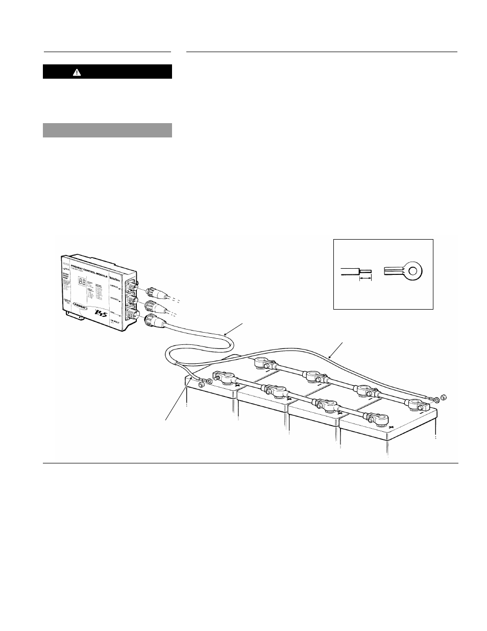
POWER CONNECTION TO BATTERIES
1.
Route wire harness from PCM to the battery. Cut the harness to length
as required.
2.
Strip outer wire jacket of harness back to expose the positive (red) and
negative (black) leads. Strip the leads as shown and crimp the ring
tongue terminals supplied to the wires. Connect the leads to the battery
terminals. (See Figure 3-19.)
3.
Leave power harness disconnected. (See Figure 3-19.) Do not install until
PROHEAT coolant pump system has been purged of air. (See First Time
Startup, page 3-26)
NOTE: When power is connected to the PCM, all segments of the LED will flash
on the PCM. This indicates that power has been supplied. See page 5-4
for more information.
NOTE: Ensure the battery terminals are clean and free of corrosion. Remove
and clean. Prior to re-connecting grease terminals with electrically
conductive grease.
Figure 3-19
Power Connection to Battery
POWER SUPPLY
HARNESS
STRIP WIRE AS SHOWN AND
CRIMP TO TERMINAL
3/16"
RED (+) POSITIVE
BLACK (-) NEGATIVE
CAUTION
12 Volt products should not use
power split from a 24 Volt system.
This will cause uneven charging of
the batteries.
NOTICE
Systems providing heat to both engine
and sleeper require four (4) batteries.
3-11
SECTION 3. INSTALLATION
3.5.2