Proheat X45–School Bus User Manual
Page 51
PROHEAT INSTALLATION & SERVICE
4-2
to the motors and sensors. It has powerful diagnostics to assist in
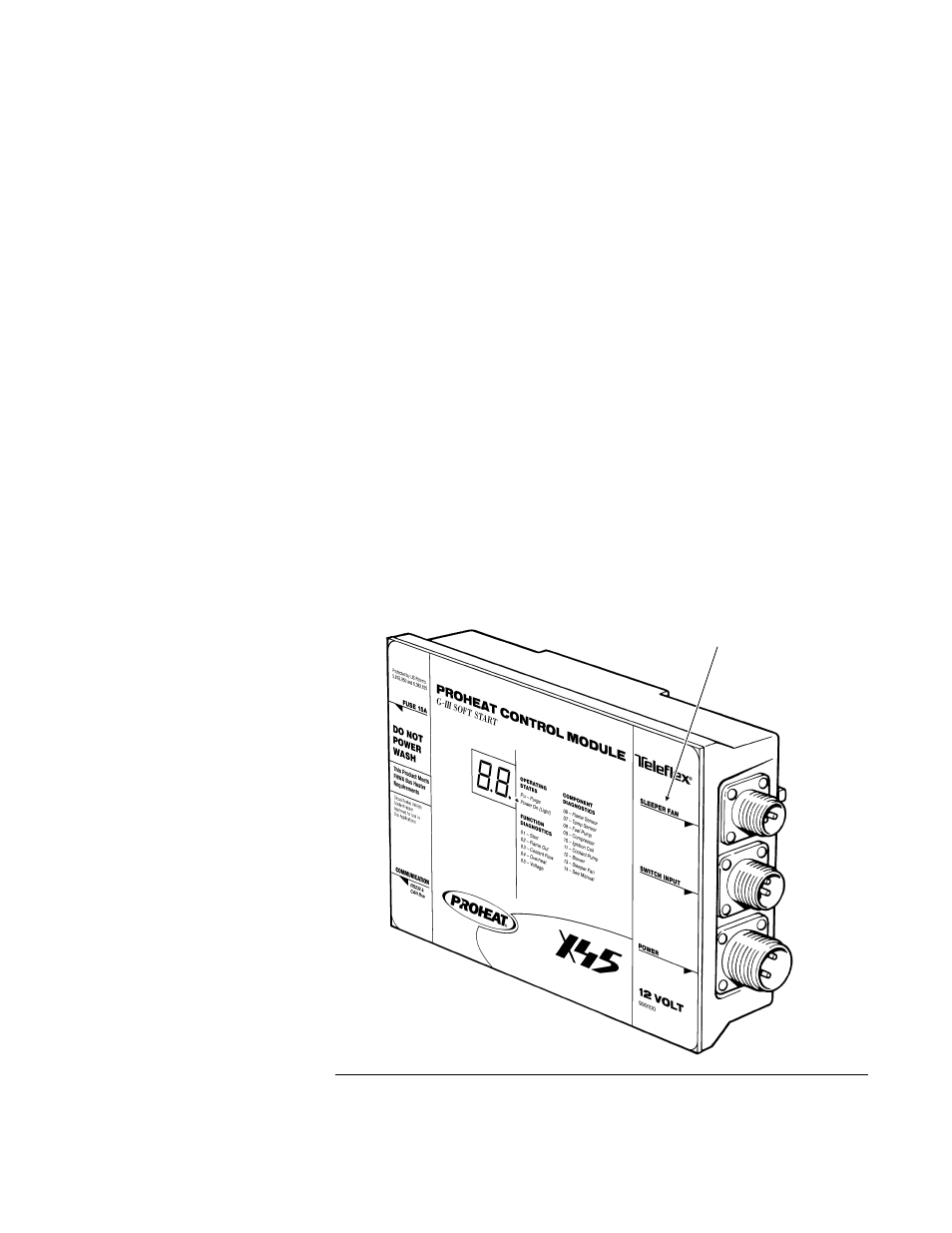
troubleshooting. One of the key features is the diagnostic display on the
front of the PCM which has a display LED to indicate function or
component problems. The PCM comes in a "Sleeper Fan 12V" or "Aux
Input 12V or 24V" model. The PCM model can be identified by looking at
the lexan decal as shown in Figure 4-2.
•
The "Sleeper Fan" model has an output with a special current limiting
feature which, if used, limits the current draw of the sleeper heater fan
to 3 Amps. This is done to control the total current draw on the vehicles
batteries. This operation is typically used for truck installations.
•
The "Aux Input" model uses two special input pins (see Electrical
Drawing on page 1-4) that allow for a Preheat Mode and Supplemental
Mode operation. This operation is typically used for transit and coach
installation.
NOTE: See "Modes of Operation Section" for a description of the operating
modes used for both the "Sleeper Fan" and "Aux Input" Models
NOTE: The PROHEAT PCM “Sleeper Fan” circuit has a one minute delay
during ignition.
NOTE: The PROHEAT PCM is unique in that it uses “ground-side” switching
for the blower, compressor, coolant pump and ignition coil. The
positive wire to the motors and ignition coil will show voltage even
when the heater is switched “OFF.”
6. PROHEAT Control
Module (PCM)
Figure 4-2
LED will light to indicate a problem. Switch or Timer indicator light will
flash to indicate the diagnostic code (page 5-3).
PCM MODEL IDENTIFICATION.
SLEEPER FAN MODEL SHOWN.