Proheat X45–School Bus User Manual
Page 38
3-17
SECTION 3. INSTALLATION
Figure 3-28
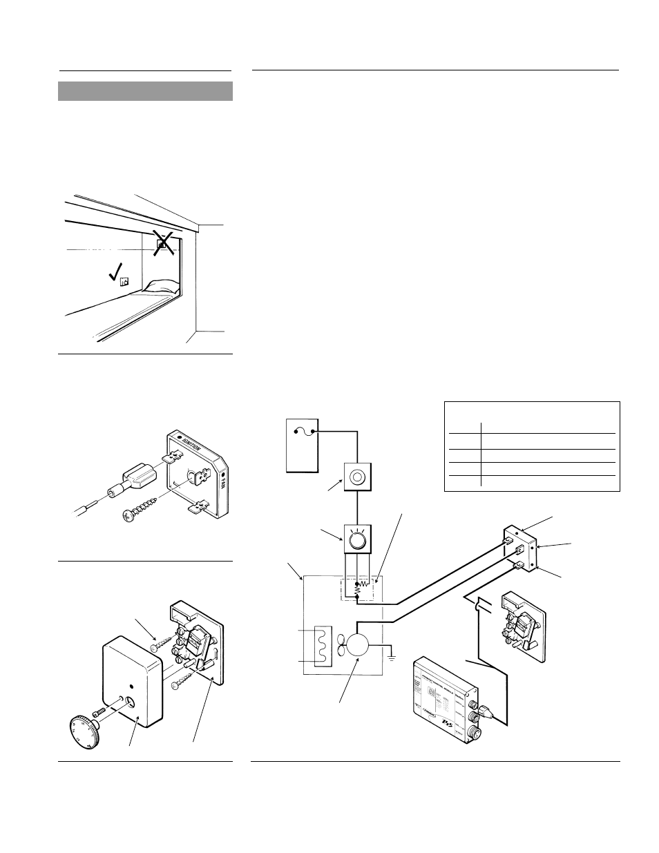
Option D
Figure 3-26
Isolator Detail
Figure 3-27
Thermostat Detail
Figure 3-25
Thermostat Location
1.
Make sure the vehicle ignition is switched “OFF.”
2.
Mount the isolator in the sleeper fan motor area to a solid metal surface
with the screw provided. Cut OEM wire to sleeper fan motor and connect
isolator in series. Connect using
1
⁄
4
" spade connectors provided. (Figure
3-26) Wire end from resistor pack connected to isolator terminal marked
“IGNITION.” Wire end from sleeper fan motor connected to isolator
terminal marked “FAN.”
3.
Locate PROHEAT thermostat in central area of sleeper, approximately 12"
above the bunk. Avoid direct air flow from sleeper fan ducts. (See Figure 3-25.)
4.
Remove the adjusting knob and face cover. Mark and drill mounting
holes. Mount thermostat using the screws provided. (Figure 3-27)
5.
Route sleeper fan harness from PCM to PROHEAT thermostat. Cut to length.
Connect white wire to terminal 1 of the thermostat. Use fork terminal provided.
Black wire not used.
6.
Route a wire from terminal 2 of the thermostat to the isolator terminal marked
“HEATER.” Connect using fork and spade terminal provided. (Can be cut from
left over wire harness.)
NOTE: For large sleepers this MAY NOT provide enough fan speed and
therefore option A, B or C should be considered.
3/16"
(5 mm)
MOUNTING SCREW
BASE
FACE
ISOLATOR
IGNITION
W
HI
TE
W
H
IT
E
FAN
HEATER
(PROHEAT)
BLACK WIRE
(NOT USED)
1
1
2
2
3
4
SLEEPER FAN
HARNESS
PROHEAT
THERMOSTAT
(SEE WIRE
CONNECTION
DETAIL)
PCM
OEM THERMOSTAT
OEM FAN
MOTOR CONTROL
(2 OR 3 SPEED)
OEM SLEEPER
HEATER ASSEMBLY
VEHICLE
FUSE PANEL
FAN MOTOR
(SINGLE WINDING TYPE)
M
RESISTOR ASSEMBLY
NOTE: MAY OR MAY NOT
BE LOCATED INSIDE
SLEEPER HEATER
ASSEMBLY
MUST BE BOLTED TO A
METAL SURFACE FOR
HEAT SINKING
Thermostat Wire Connection Detail
Screw # Wire Colour
1
White (from PCM)
2
White (to isolator)
3
Not used
4
Not used
OPTION D – Auxiliary Sleeper Heater Current Limited
3.5.9
NOTICE
Sleeper Fan output does not supply
power during ignition (1 minutes after
switch ON). DO NOT use for controlling
coolant valves. DO NOT use for
controlling coolant valves. See page
4-5 for operational sequence
information.