Notice, Fuel system – step 3 – Proheat X45–School Bus User Manual
Page 65
PROHEAT INSTALLATION & SERVICE
5-8
Fuel System – Step 3
Check:
Vehicle Fuel Supply, Fuel Pump
a)
Vehicle fuel level and/or for fuel gelling during cold weather.
b)
Air leaks and/or restrictions in the fuel supply lines to the
PROHEAT.
c)
The PROHEAT operation when supplying fuel from a direct
source.
Test Procedure — Fuel Supply Inspection:
a)
Is there fuel in the tank?
b)
Check fuel lines, connections and routing back to the fuel tank
for kinks, loose fittings, stiff lines or cuts.
Replace any fuel lines that are cut, brittle or chaffed.
Test Procedure — Fuel Pump Inspection:
a)
Disconnect the fuel line at the inlet to the regulator and place
into a cup.
b)
Start PROHEAT. Ensure that fuel flows out of the fuel line in a
steady, uninterrupted and clear stream of fuel.
c)
If fuel does not flow, check filter and relief valve for contamination
as per Service Bulletin SB0062. (See appendices page 7-1.)
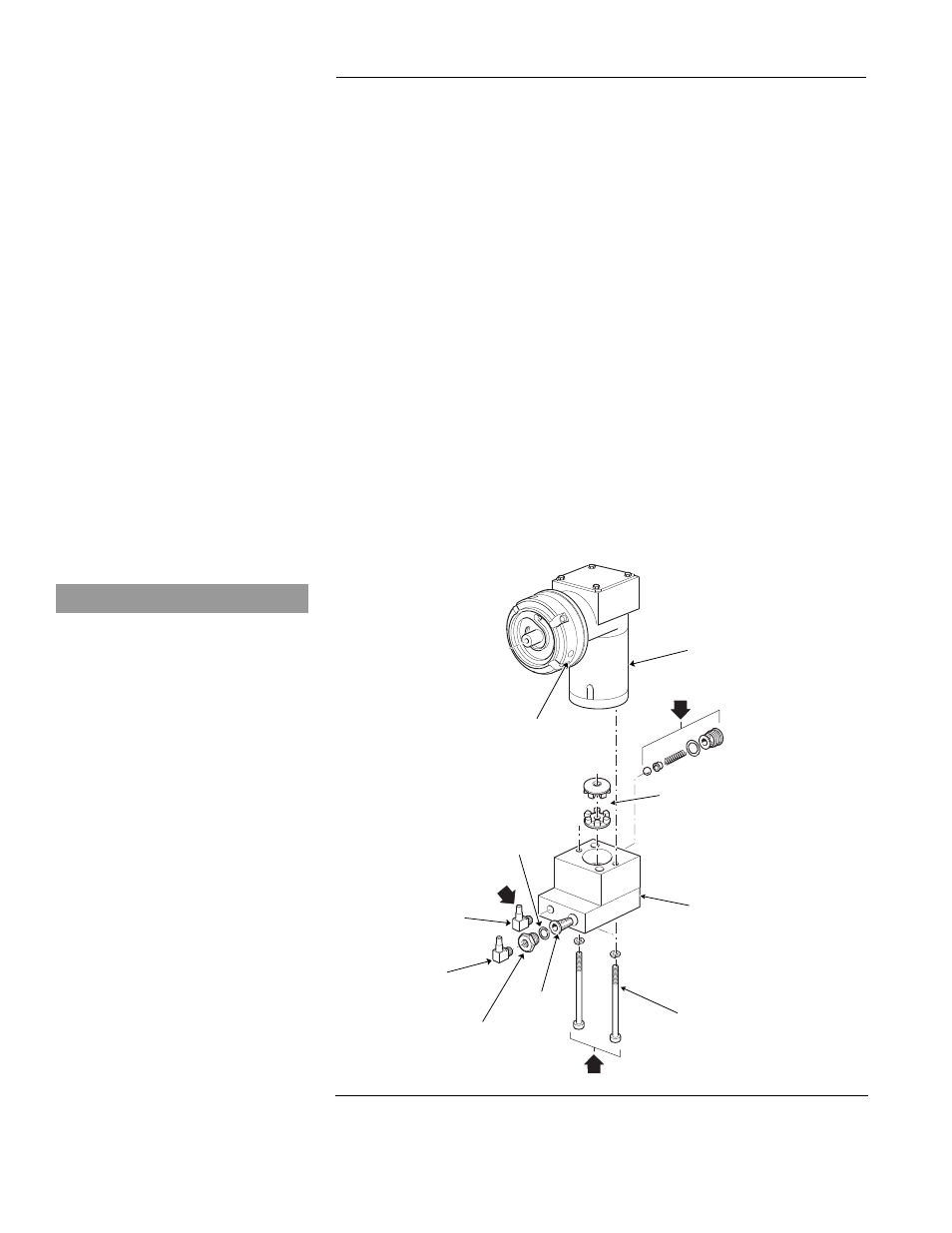
Figure 5-5
Compressor / Fuel Pump Assembly
A
B
C
COMPRESSOR
DRIVE COUPLING X 2
FUEL PUMP
RELIEF VALVE
BOLTS X 2
INLET
FITTING
PRESSURE
ADJUSTING SCREW
“O” RING
FILTER
OUTLET
FITTING
ADAPTER
A
• Apply Loctite 242 to threads
• Torque bolts (2) to 25±3 in/lbs
(2.8±0.3 Nm).
B
• Lubricate o-ring with diesel fuel
• Torque relief valve to 22±2 in/lbs
(2.5±0.2 Nm).
C
• Apply Loctite 59241 sealant to
threads.
• Torque elbow (1) to 55±5 in/lbs
(6.2±0.5 Nm) minimum or until
elbow is at correct orientation.
NOTICE