Notice, Warning – Proheat X45–School Bus User Manual
Page 66
SECTION 5. TROUBLESHOOTING & REPAIR
5-9
Fuel System – Step 4
Check:
Air Compressor
a)
Air compressor pressure and operation
Test Procedure — Air Compressor pressure:
a)
Run heater until warm to the touch. This ensures the heater
components are up to normal operating temperature.
b)
Switch heater off.
c)
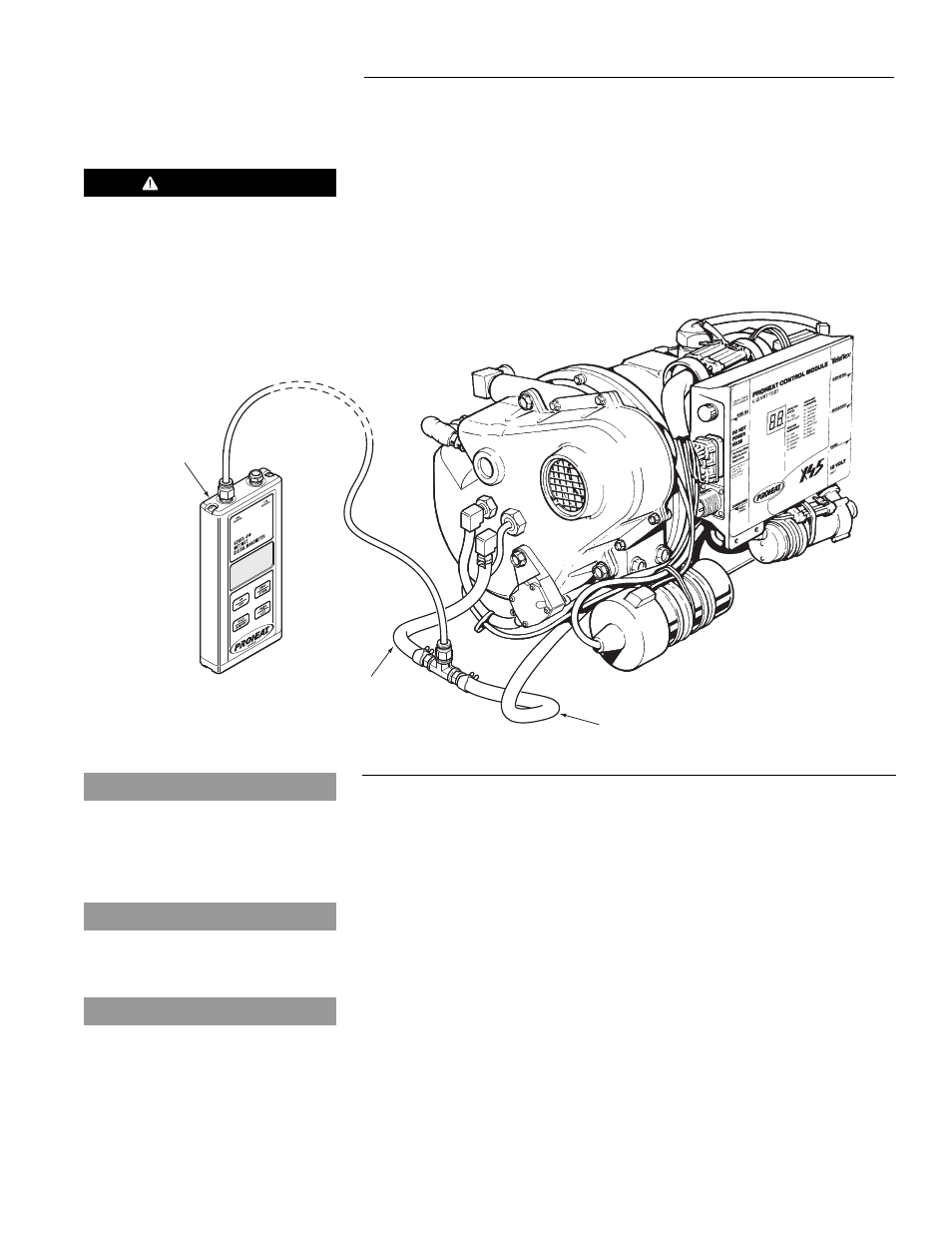
Install PK0037 Digital Manometer (or a calibrated PK0060
Analog Air pressure gauge) in-line as shown in Figure 5-6.
HOSE TO
NOZZLE AIR
INLET
DIGITAL
MANOMETER
PK0037
HOSE FROM COMPRESSOR
Figure 5-6
d)
Locate the rubber boot on the positive end of the ignition coil
and peel it back to expose the positive terminal.
e)
Select the DC Volts range of a multimeter and connect as per
Figure B. The positive lead of the multimeter should be
attached to the positive coil lead. The negative lead of the
multimeter should be attached to the heater chassis at the
PROHEAT ground boss.
f)
With the heater running in full output (flame on and ignition is
off) read the voltage and refer to the 12 or 24 volt chart (Figure
5-8 and Figure 5-9) for the correct Air Pressure Reading.
g)
The reading must be within the range of the shaded area as
shown in Figure 5-8 and Figure 5-9.
NOTICE
If using PK0060, Analog Air pressure
gauge, calibrate gauge before each
use refer to:
www.proheat.com/PDFs/990614.pdf
NOTICE
Altitude Correction is needed above
3000 Feet (see inset on charts).
DO NOT adjust air pressure when
above 6000 Feet.
NOTICE
Remove Pressure Gauge when finished
with measuring & setting procedure.
WARNING
Shock hazard due to high secondary
coil voltage.