Timer connections (optional), Caution, Notice – Proheat X45–School Bus User Manual
Page 33
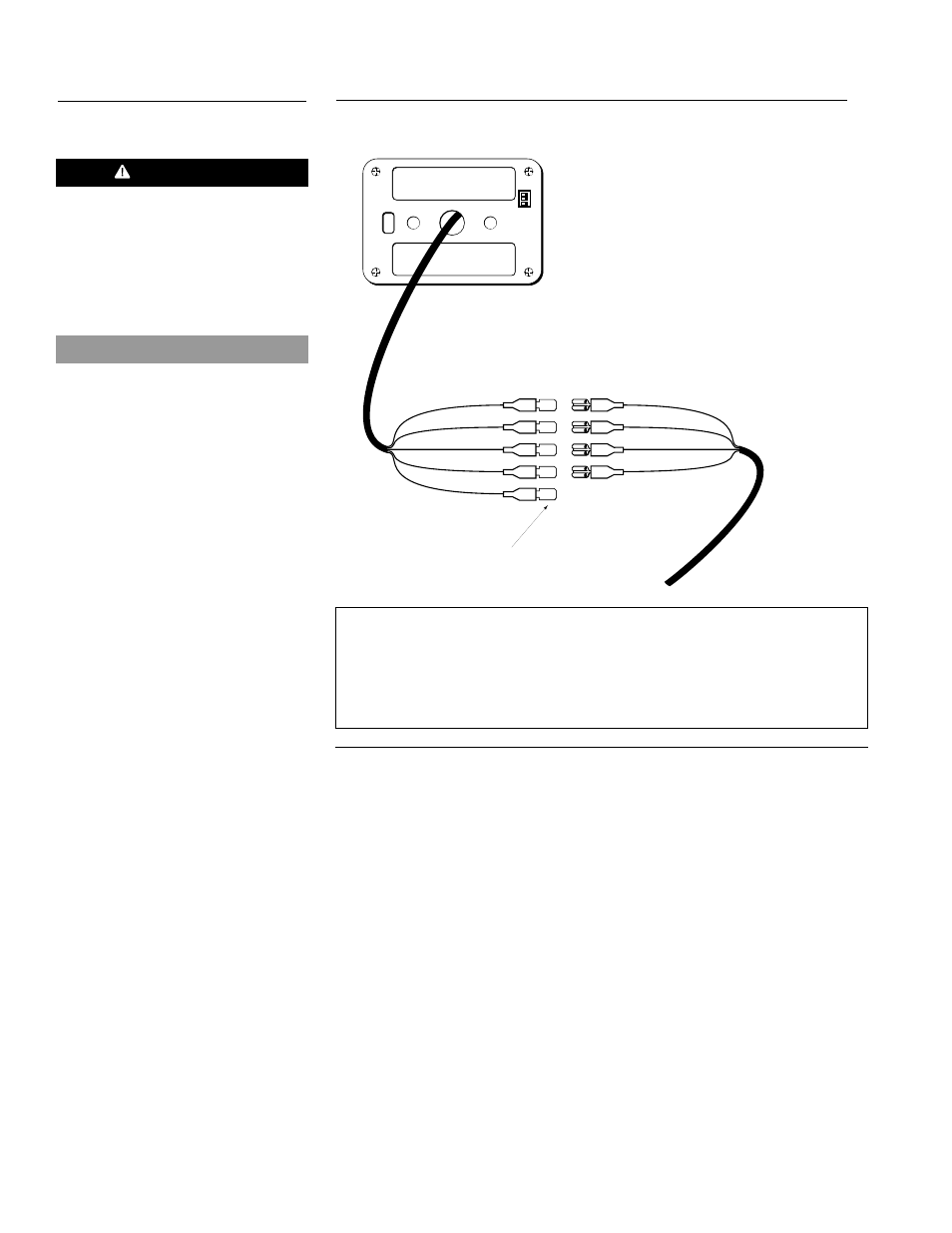
Figure 3-20
Timer Connections
T
IM
E
R
1
O
N
2
3
BLACK
RED
WHITE
GREEN
BLACK
TIMER
SWITCH INPUT
HARNESS
RED
WHITE
GREEN
GREY
TO KEYSWITCH (OPTIONAL)
TIMER CONNECTIONS (OPTIONAL)
Black wire
Ground
Red wire
Power
White wire
Operational signal from heater
Green wire
“ON” Signal to heater
Grey wire
Keyswitch backlighting (optional)
CAUTION
The switch input circuit should only
be used to supply power to the
ON/OFF Switch, the Timer, or as a
signal to trip a relay. Failure to
follow this installation practice will
result in damage to the PCM.
NOTICE
The PCM must be reset (power
disconnected and reconnected)
when changing from a Timer to an
ON/OFF Switch or from an ON/OFF
Switch to a Timer.
Do not connect an ON/OFF Switch
and a Timer in the same circuit.
3-12
PROHEAT INSTALLATION & SERVICE
3.5.3