Proheat X45–School Bus User Manual
Page 53
The electrode is located near the nozzle just out of the air/fuel mixture path.
During the ignition sequence the spark jumps the gap between the electrode and
the combustion tube, igniting the air/fuel mixture. Spark duration is 60 seconds.
Measures coolant temperature at the outlet port of the heat exchanger.
Protects the heater from damage should it be operated without coolant. The
overheat breaker monitors the surface temperature of the heat exchanger casting.
When the temperature reaches 286˚F (141˚C) the breaker “trips out.” This shuts
off the power to the air compressor—extinguishing the flame. The breaker can
be reset by pushing down on the red button (located under the rubber cap).
Photo-electrically measures the intensity of the flame. It is the flame sensor
that signals to the PCM that the air/fuel mixture is burning properly.
Is used to switch the heater “ON” and “OFF.” It has an indicator lamp that
displays a red light when switched “ON.” A flashing red light indicates a heater
diagnostic code and one of the LEDs on the PCM diagnostic display will be lit.
(See page 5-3 for details.)
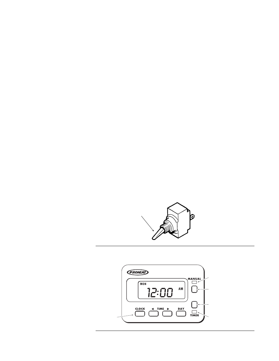
Is used to switch the heater “ON” and “OFF.” This can be done manually or by
a preset time and day. It has an indicator lamp that displays a red light when
switched or timed “ON.” A flashing red light indicates a heater diagnostic code
and one of the LEDs on the PCM diagnostic display will be lit. (See page 5-3
for details.)
On Sleeper Fan 12 V models (see page 4-2), the Proheat Control Module is
equipped with a 3 A limited output. It is used to drive fans or other equipment
as determined by the installation (see page 3-1). The output is ON 60 seconds
after switch ON. In addition, it is also ON when there is a functional error (see
page 5-1 for details).
12. Coolant Temperature
Sensor
11. Ignition Electrode
13. Overheat Breaker
Sensor
14. Flame Sensor
15. On/Off Switch
16. 7 Day Timer
17. Sleeper Fan
(only output connector
shown)
T-II
CLOCK
TIMER ID LIGHT
(GREEN)
INDICATOR LIGHT
(RED)
TIMER SET
BUTTON
MANUAL
BUTTON
Figure 4-5
7 Day Timer
Figure 4-4
ON/OFF Switch
Indicator Light
Located in the Toggle
4-4
PROHEAT INSTALLATION & SERVICE