6b - water connections - ntv water heater, 6b.1 ntv water quality, 6b.2 piping requirements – LAARS NeoTherm NTV (Sizes 150–850 MBTU/h) - Install and Operating Manual User Manual
Page 30
Page 26
LAARS Heating Systems
6B.2 Piping Requirements
Water piping should be supported by suitable hangers and
floor stands. Do not support piping with the appliance. Due
to expansion and contraction of copper pipe, consideration
should be given to the type of hangers and supports used.
Rigid hangers may transmit noise through the system resulting
from piping sliding in the hangers. It is recommended that
padding be used when rigid hangers are installed. Maintain 1”
(2.5cm) clearance to combustibles for hot water pipes.
Pipe the discharge of the relief valve (full size) to the drain or
in a manner to prevent injury in the event of pressure relief.
Install a diaphragm-type expansion tank, flow check, and
shutoff valves where needed or as required by code.
NeoTherm 150-500 can be ordered with pumps. Whether the
factory pumps or other pumps are installed the piping should
be installed such that the pump supplies flow to the heater it
is attached to only. The factory pumps are sized for 30 feet
and 6 elbows of total pipe length, so the heater should be
placed within 15 feet of the tank. If longer runs are required, a
properly-sized field-supplied pump should be used.
Section 6B -
WATER CONNECTIONS -
NTV WATER HEATER
Section 6 is divided into two parts. Section
6A covers NTH units designed for hydronic
heating. Section 6B covers NTV models, which
are designed exclusively for “volume water”
domestic hot water applications. Refer to the
proper section for instructions on installing
and piping your product. Refer to Table 9 for
the connection pipe sizes required.
6B.1 NTV Water Quality
NTV water heaters must be installed in water conditions
of 10gpg hardness or less with a pH range of 8.2 to 9.5.
Operating the NTV in water with higher hardness levels will
cause heat exchanger fouling, erosion, or corrosion leading
to premature component failure, reduced efficiency, heat
exchanger failure or system failure. Failure of this type will
not be warranted. If the water in use exceeds the conditions
recommended, a water softener or other device should be
installed to improve water quality.
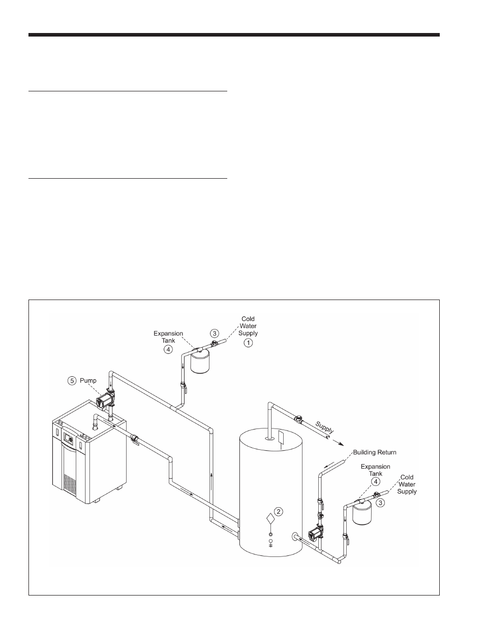
Figure 22 - DHW Piping, One Heater, One Vertical Tank
NOTES:
1. Optional CWMU & Recirc. line location.
2. Locate NTV DHW sensor or remote aquastat well
in lower 1/3 of tank.
3. Back flow preventer may be required - check local codes.
4. Thermal expansion tank may be required - check local codes.
5. Factory mounted pumps are sized for a max pipe length of
30’ total, 6-90° elbows, full pipe size.
6.
Caution: Pump sizing must be based on water hardness at job site.
WARNING: This drawing shows
suggested piping configuration and
valving. Check with local codes and
ordinances for additional requirements.