Automatic run test, 10 table 6 — quick access chart – Carrier OMNIZONE 50XJ064-104 User Manual
Page 10
10
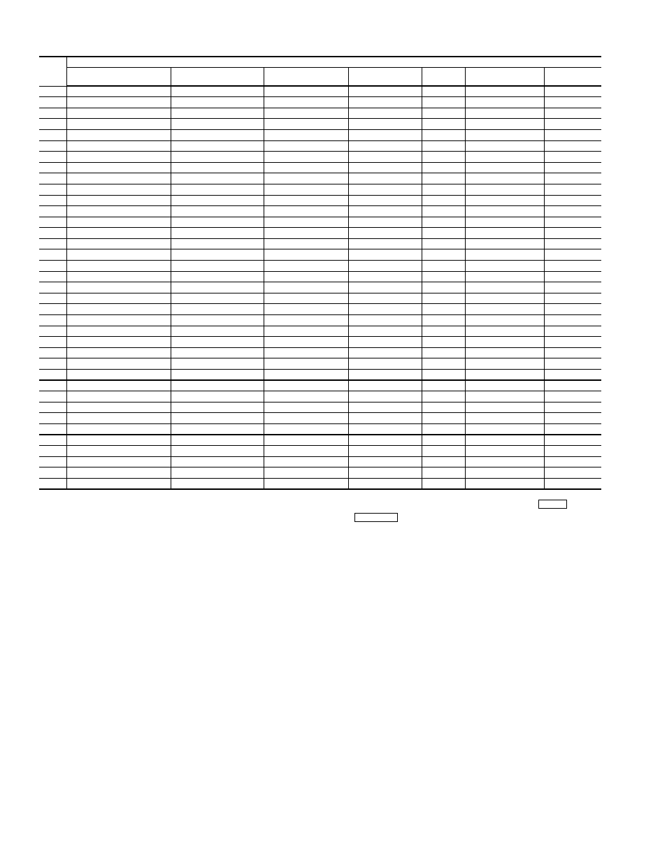
Table 6 — Quick Access Chart
LEGEND
NOTES:
1. To change from Edit mode to Status mode, press
or press
again.
2. Not all available selections will have items to select in sublevels.
Automatic Run Test —
The 50BV,XJ unit controls are
programmed with an automatic run test that checks connection
and operation of major components. To perform the run test:
Verify that the control display (LID device/System Monitor)
interface cable is connected to internal jack on main controller;
that the fire alarm/shutdown switch input (FSD) has a factory
jumper or field input; that Bypass (if installed) is set in the
DRIVE position; and that the Local/Off/Remote switch is set to
the REMOTE position.
NOTE: When the Local/Off/Remote switch is in the
REMOTE position, the controller time schedule is pre-set
(from the factory) as unoccupied. This means that the unit
will not turn on until the run test is enabled. However, if the
controller schedule has already been modified in the field,
and the current time of day is occupied, then the supply fan
will start. The run test will shut the fan down when it
begins. The run test will complete and then the supply will
automatically restart.
NOTE: If the Local/Off/Remote switch is in the OFF posi-
tion, it is normal for the red alarm light on the display panel
to be lit, indicating that the unit is disabled.
NOTE: If the red light stays on when the switch is moved to
REMOTE, or if any other problems occur during the run
test, refer to the Troubleshooting section of this manual.
To perform the Run Test:
1. Turn unit power on.
The LID display will show the controller identifica-
tion, time and date (Fig. 5):
OMNIZONE VPAC
hh:mm mm-dd-yy
LID
NUM.
KEY
LID FUNCTION KEYS
Algorithms
(ALGO)
Status
(STAT)
History
(HIST)
Service
(SRVC)
Alarm
(ALRM)
Setup
(SET)
Schedules
(SCHD)
1
AO—Adaptive Control
Hardware Points
Alarm History
Function Definition
Limit
Set Clock
Occupancy
2
AO—Cooling CV
Software Points
Analog Point Trace
Channel Definition
Setpoint
Real Time Clock
Setpoint
3
AO—Cooling VAV
Temperature Input
Discrete Point Trace
System Definition
Discrete
Controller Password
Holiday
4
AO—Fan Tracking
Milliamp Input
Consumable Channel
Setpoint Definition
First out
N/A
S/W Setpoint
5
AO—Heating CV
Custom Milliamp Input
Internal Consumable
Database Control
Runtime
N/A
Network Time
6
AO—Heating VAV
Voltage Input
Runtime Channel
Comfort Controller
# of starts
N/A
N/A
7
AO—Humidity Control
Custom Voltage Input
N/A
CCN Control
N/A
N/A
N/A
8
AO—Mixed Air CV w/IAQ
Sensed Discrete Input
N/A
LID Preferences
N/A
N/A
N/A
9
AO—Mixed Air VAV w/IAQ
Latched Discrete Input
N/A
N/A
N/A
N/A
N/A
10
AO—Permissive Interlock
Pulsed Discrete Input
N/A
N/A
N/A
N/A
N/A
11
AO—Reset
Milliamp Output
N/A
N/A
N/A
N/A
N/A
12
AO—Shared Transducer
Custom Milliamp Output
N/A
N/A
N/A
N/A
N/A
13
AO—Static Pressure
Voltage Output
N/A
N/A
N/A
N/A
N/A
14
DO—Analog
Custom Voltage Output
N/A
N/A
N/A
N/A
N/A
15
DO—DX-Staging VAV
Discrete Output
N/A
N/A
N/A
N/A
N/A
16
DO—Electric Heat CV
Stepper Motor Output
N/A
N/A
N/A
N/A
N/A
17
DO—Electric Heat VAV
Discrete Software Point
N/A
N/A
N/A
N/A
N/A
18
DO—Enthalpy Comparison
Analog Software Point
N/A
N/A
N/A
N/A
N/A
19
DO—Interlock
Network Data Out
N/A
N/A
N/A
N/A
N/A
20
DO—Lighting Control
Network Data In
N/A
N/A
N/A
N/A
N/A
21
DO—Permissive Interlock
N/A
N/A
N/A
N/A
N/A
N/A
22
DO—Pump Control
N/A
N/A
N/A
N/A
N/A
N/A
23
DO—Prop Thermo
N/A
N/A
N/A
N/A
N/A
N/A
24
DO—Prop Thermo 2 Pipe
N/A
N/A
N/A
N/A
N/A
N/A
25
DO—Prop Thermo 4 Pipe
N/A
N/A
N/A
N/A
N/A
N/A
26
DO—Staged Thermostat
N/A
N/A
N/A
N/A
N/A
N/A
27
DO—Staging Control
N/A
N/A
N/A
N/A
N/A
N/A
28
DO—Time Clock
N/A
N/A
N/A
N/A
N/A
N/A
29
DO—Time Clock w/Check
N/A
N/A
N/A
N/A
N/A
N/A
30
AOSS Schedule
N/A
N/A
N/A
N/A
N/A
N/A
31
Network Broadcast
N/A
N/A
N/A
N/A
N/A
N/A
32
Linkage/AOSS Schedule
N/A
N/A
N/A
N/A
N/A
N/A
33
NTFC w/Enthalpy Check
N/A
N/A
N/A
N/A
N/A
N/A
34
Sensor Group
N/A
N/A
N/A
N/A
N/A
N/A
35
WSM Air Source
N/A
N/A
N/A
N/A
N/A
N/A
36
WSM Cool Source
N/A
N/A
N/A
N/A
N/A
N/A
37
Custom Program
N/A
N/A
N/A
N/A
N/A
N/A
AO
— Analog Output
AOSS — Adaptive Optimal Start/Stop
CV
— Constant Volume
DO
— Digital Output
IAQ
— Indoor Air Quality
N/A
— Not Available
NTFC
— Nighttime Free Cooling
VAV
— Variable Air Volume
WSM
— Water System Manager
CLEAR
EXPN/EDIT