Hardware description – Cabletron Systems DMS-100 User Manual
Page 28
28 Chapter 1: Introduction to the EIU
297-8991-910 Standard 03.01 August 1999
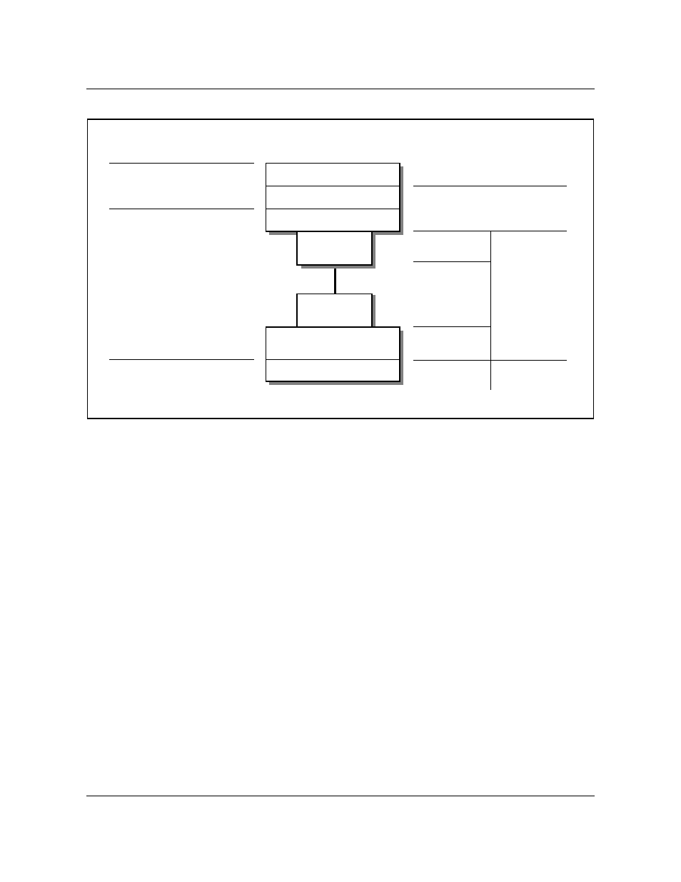
Figure 3
EIU mapping to lower levels of the OSI communications model
Hardware description
The EIU is based on hardware originally developed for the signaling transfer
point (STP). One of the main components of the STP is the LPP, which is a
frame that can hold up to 36 two-slot ASUs. An LPP containing an EIU is
deployed in a DMS SuperNode switch to establish Ethernet connectivity.
Figure 4 on page 29 shows where the EIU is provisionable on the link interface
shelf (LIS). Figure 5 on page 30 shows where the EIU is provisionable on the
single-shelf link peripheral processor (SSLPP).
The EIU consists of three cards provisioned in two slots, as shown in figure 4
and figure 5:
•
NT9X84AA, Ethernet interface card (EIC). This processor board
implements most of the media access control (MAC) layer on a single chip.
It has 384 kbyte of high-speed buffer for holding Ethernet packets.
•
NT9X85AA, Ethernet interface paddle board (EIP). This paddle board
provides the physical link to the local area network (LAN). The paddle
board implements an unshielded twisted-pair attachment unit interface
(AUI).
•
NTEX22BA/BB, Integrated processor and F-bus card (IPF). This
processor board contains a Motorola M68020 processor and 8 Mbyte of
RG-58 coaxial
cable
Attachment
unit interface
OSI reference model layers
Data link Layer
Physical Layer
Media access control
Logical link control
Physical signaling
EIU partitioning
EIU software
AUI PB
Ethernet interface hardware
Attachment
unit interface
15-conductor
connectorized
cable
Media access unit
Transmission medium
UTP PB
External
equipment
4-wire twisted
pair, LAN hub