Cabletron Systems DMS-100 User Manual
Page 170
170 Appendix F: EIU supported configurations
297-8991-910 Standard 03.01 August 1999
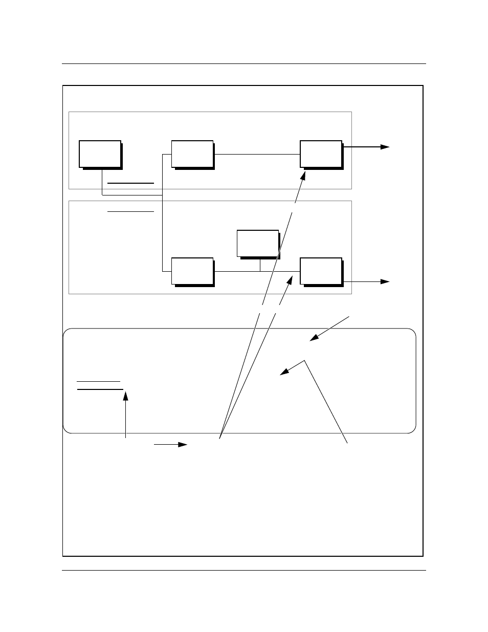
Figure 43
Interface Configuration part 2
TABLE LIUINV
EIU 1 LIM 0 1 26 ERS09BB NTEX22BB NT9X84AA NT9X85AA YES 000075F17009
EIU 2 LIM 0 2 14 ERS09BB NTEX22BB NT9X84AA NT9X85AA YES 000075F17015
TABLE IPNETWRK
1 47 105 150 1 12 $ (EIU_INTERFACE EIU 1) (DFLT_INTERFACE Y) (DFLT_GTWY_IPADDR 47 105 150 3)
2 47 105 160 1 12 $ (EIU_INTERFACE EIU 2) (DFLT_GTWY_IPADDR 47 105 160 3)
TABLE IPHOST
0 CM 0 64 32 32
Can be another
subnet or new
network on this
side of external
router
classA
.
networkidB
.
subnetX
.
hostZ
47.105.150.1
47.105.160.2
47.105.150.3
External
router
Subnet 1
Base_Tel-4
Host
EIU 1
CM
255.255.240.0 router mask
Default EIU
SubnetX size
MAC address
Can be another
subnet or new
network on this
side of external
router
47.105.160.3
External
router
Subnet 2
EIU 2
47.105.160.1
classA
.
networkidB
.
subnetY
.
hostZ
Note: The CM node can support up to 16 different IP addresses.
- FOT-F3 (41 pages)
- FOT-F3 (44 pages)
- BRIM-F6 (41 pages)
- WPIM-RT1 (50 pages)
- BRIM-WT1 (32 pages)
- 36 (33 pages)
- 9T101-04 (28 pages)
- FDDI Repeater (29 pages)
- SWPIM-BRI (34 pages)
- 9C114 (26 pages)
- SMARTSWITCH ROUTER 9032578-05 (398 pages)
- HSIM-W6 (258 pages)
- NB25 E (30 pages)
- HSIM-G01 (36 pages)
- HSIM-FE6 (42 pages)
- Expansion module 9E429-36 (18 pages)
- EMM-E6 Ethernet (205 pages)
- Environmental Module TM 9C300-1 (50 pages)
- CSMIM-T1 (198 pages)
- NBR-620 (73 pages)
- E2100 (42 pages)
- KBU64 Rackmount (26 pages)
- AirConnect 3Com (93 pages)
- 802.1Q (92 pages)
- W85 (60 pages)
- ELS10-26 (170 pages)
- Expansion module 9E106-06 (40 pages)
- 6H259-17 (58 pages)
- Expansion module 9F120-08 (12 pages)
- EMC39-12 (33 pages)
- 6A000/ZX-250 (268 pages)
- Expansion module DELHE-UA (50 pages)
- Expansion module 9T122-08 (36 pages)
- BRIM E100 BRIM-E100 (42 pages)
- Cabletron CyberSWITCH CSX400 (275 pages)
- Cabletron SmartSwitch Router 250 (34 pages)
- Network Router (100 pages)
- 9W111-08 (28 pages)
- CSX400 (101 pages)
- Cabletron SmartSwitch Router 510 (106 pages)
- SEHI-32/34 (90 pages)
- SmartSwitch (338 pages)
- 9T106-01 (28 pages)
- Switch 9H531-17 (38 pages)