Interlogix NX-590NE User Manual
Page 10
8
NX-590NE Internet Interface Installation Manual
2. Connect the J3 screw terminals or the J19 plug terminal to the control panel
keypad databus.
J3 pins
J19 pins
Pin 1 - NX bus (Data)
Pin 1 - +12VDC
Pin 2 - Ground
Pin 2 - No connection
Pin 3 - +12 VDC
Pin 3 - Ground
Pin 4 - NX bus (Data)
Note: The J6 console (DB-9 female) is used by the factory to troubleshoot and
test the board. The J9 PIC upgrade connector is used for future upgrades to the
PIC processor.
Table 1 below shows the minimum wire gauge and maximum wire length allowed
for the NX-590NE.
Table 1: Minimum wire gauge by length
Length in feet
250
500
1000
2000
Connected to NX panel
22
20
16
14
Connected to NX-320E
22
18
16
12
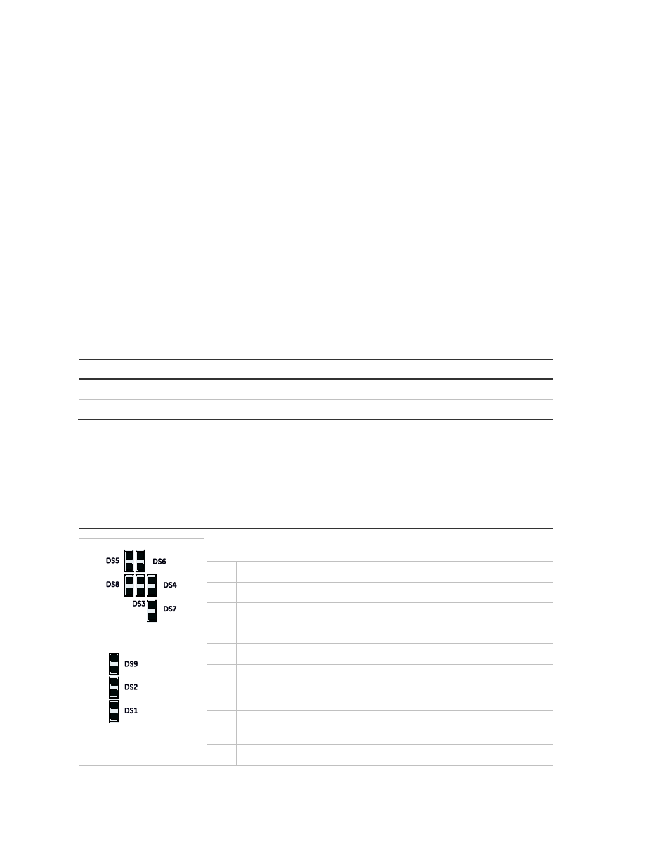
LEDs
Table 2 below describes the LEDs on the NX-590NE board
Table 2: NX-590NE LED indicators
LED
Description
DS1 Flashes each time the NX-590NE has an opportunity to access
the NetworX bus. It should flash about two times per second.
DS2 Flashes when communicating with NX bus (Data).
DS3 Flashes when waiting for UCSIMM acknowledgment.
DS4 Flashes when waiting for NX bus (Data) reply.
DS5 Flashes when message received from NX bus (Data).
DS6 Flashes when message sent to NX bus (Data).
DS7 On when U-Boot is running. Flashes when U-Boot is stopped,
either an error has occurred or stopped via console. Off during
application.
DS8 On when uClinux Kernel coming up, then shows an application
heartbeat.
DS9 On when power is on.
Table 3 on page 9 describes the LEDs on the UCSIMM module