Great Planes Spirit 100 Sailplane Kit - GPMA0550 User Manual
Page 46
(Make sure the arm is in its neutral position - approx. 15 - 20
degrees forward). Make a Z-bend in the wire with the first bend
starting where the mark is. Cut any excess wire off 1/4" past the
Z-bend. Un-snap the clevis from the control horn and insert the
Z-bend into the outer hole of servo arm. Replace the clevis on the
control horn and check the movement of the aileron to make sure
the pushrod does not bind throughout the aileron movement. You
can bend the pushrod slightly as shown in the photo if needed, but
try not to bend the threaded portion.
neutral position (the servo arm should be rotated approx. 20 to 30
degrees rearward), mark where the flap linkage crosses the outer
hole in the flap servo arm. Remove the flap linkage and make a
Z-bend starting where the mark is. Re-install the (flap linkage and
check the operation of the flaps to make sure there is no binding
throughout the full flap movement (10 degrees up and 90 degrees
down). Also check to see the flaps are even with each other and
move the same amount. If not, adjust the nylon swivels or
clevises until they are. NOTE: To separate the wing panels, just
unsnap the right clevis and leave the flap linkage connected to the
left wing. Keep an eye on the nylon clevises and replace them
when they start showing signs of wear.
HINT - Use a 2-56 tap to tap the nylon control horns and
swivel clevises before threading them on the wires. It
makes them much easier to put on and adjust.
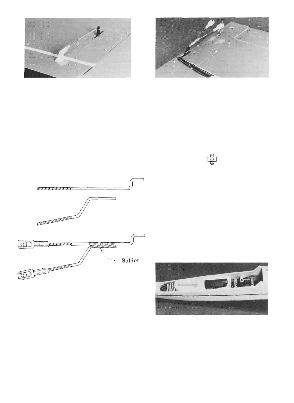
D 11. Use the remaining two 12" Threaded Wire Rods
(WIRES 16) to bend the flap pushrods according to the sketch but
don't add the Z-bend yet. Clean the wires thoroughly with
alcohol. Hold the two wires together and wrap the joint with a thin
wire and then flow solder onto the joint. Screw a Nylon Swivel
Clevis (NYLON21) onto each threaded portion of the flap link-
age.
D 13. Pack the receiver in at least 1/4" of foam and install it
between formers F3 and F4. If you are installing spoilers, put the
receiver behind the ballast box. The receiver antenna can run
down through the fuse but try to route it as far away from the
servos and servo wires as possible. Allow the excess antenna to
trail from the fuse. DO NOT CUT THE ANTENNA!
D 14. The receiver switch can be taped wherever it fits best
inside the fuse with double sided foam tape. Because the canopy
is so easy to remove, there is no need for the switch to be
accessible from the outside (this helps cut down on aerodynamic
drag and accidental shut-offs during launching as well).
D 15. The battery pack should be wrapped in 1/4" of foam also
and it should be positioned between formers F2 and F3.
D 12. Screw a Nylon Clevis Swivel (NYLON20) onto the
threaded portion of each torque rod until the little pins are approx.
5/8" from the surface of the wing. Snap the flap linkage into place
on the torque rods. With the flaps and the flap servo in their
D 16. Hook up your radio system and test the operation of all
controls. The controls should move smoothly without any
binding or looseness.
46