Build the outer wing panel, T-pins work surface, Spar – Great Planes Spirit 100 Sailplane Kit - GPMA0550 User Manual
Page 26
t h e fit, glue it in place with either med or thick CA or epoxy Add
1/4 balsa triangle along the spar and a fillet of glue along the LE
DD 25. Glue the remaining W1A and W1B ribs in place. The
second W1A should be against the wing bolt plate Glue the
bottom sheeting to each of these ribs and cut off any excess
sheeting, spars, LE, or sub TE flush with the end W1 rib
BUILD THE OUTER WING PANEL
You'll need the following parts:
SPT1W07 1/16" Balsa DC Wing Ribs - W4, W6,
W7, W9
SPT1W08 1/16 Balsa DC Wing Ribs - W2A & B,
W5,W8,W10
SPT1W13 1/8" x 3/8" x 23-1/2" Basswood Outer
Spars
SPT1W14 Shaped Balsa Leading Edge
SPT1W19 3/8 Balsa Outer Sub Trailing Edge
SPT1W23 7/8 Shaped Balsa Wing Tip Block
SPT1W24 1/16 Balsa Shear Webs
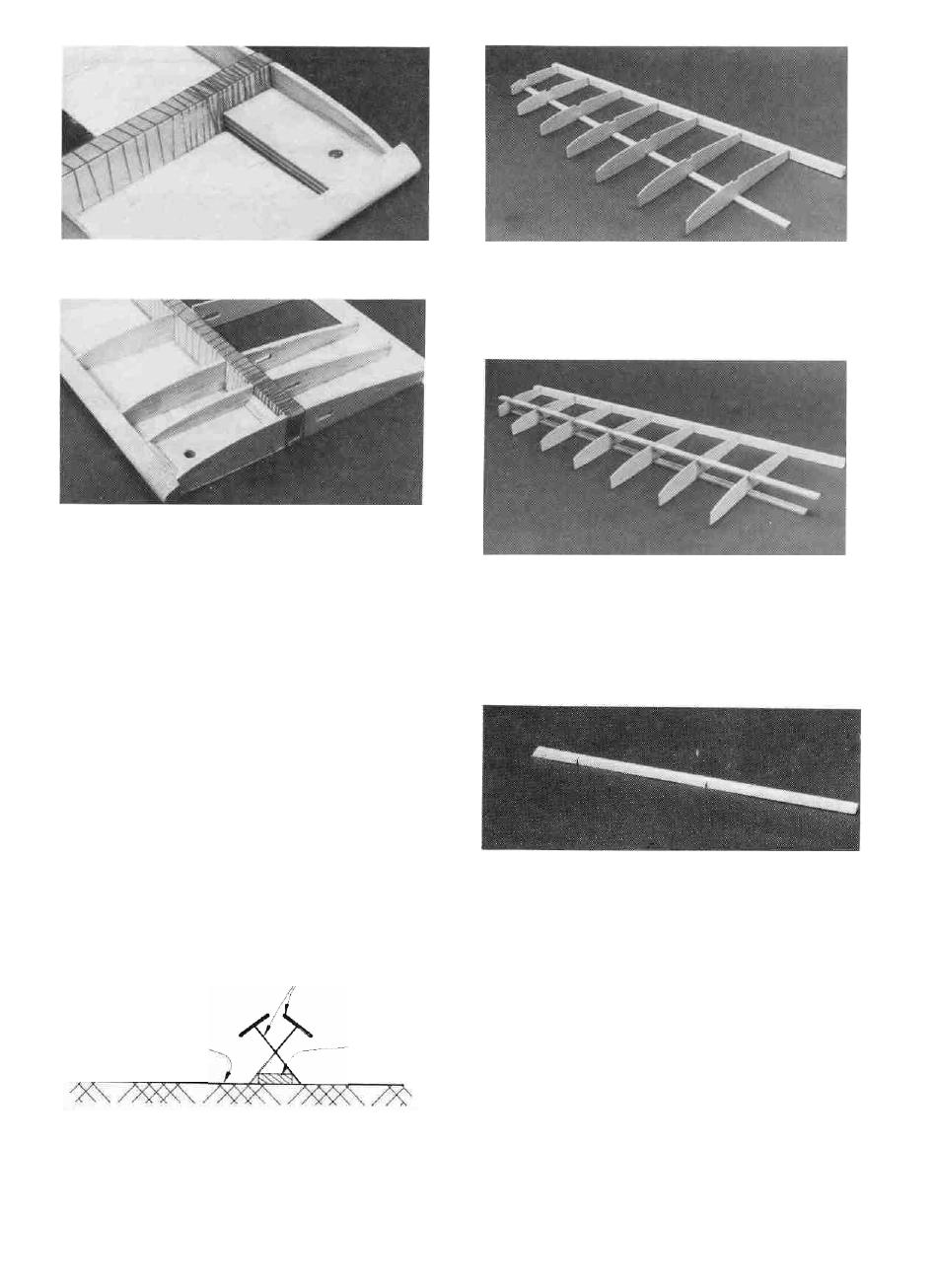
D D 1 Lay one of the Balsa Outer Sub Trailing Edges
(SPT1W19) in place over the plan Align the notches in the
trailing edge with the notches on the plans and pin it in position
T-Pins
Work Surface
D D 2 "Cross pin" one of the 1/8" x 3/8" x 23-1/2" Bass-
wood Outer Spars (SPT1W13) in place.
Spar
DD 3 Locale the 1/16" (W4 - W10) Outer Panel Ribs
(SPT1W03 & W04) and position them on the spar Glue the ribs
in place with med or thick CA at the spar joint and a drop of thin
CA at the sub TE joint Use the rib gauge to keep the ribs
perpendicular to the work surface
D D 4 Trial f i t the Top 1/8" x 3/8" x 23-1/2" Basswood
Outer Spar (SPT1W13) in place by carefully pressing the spar
into the notches until i t is flush with the top of the ribs Remove
the spar and apply med or thick CA to the notches Replace the
spar and allow the glue to cure.
D D 5 Lay a Pre-Shaped Balsa Leading Edge (SPT1W14)
over the LEADING EDGE TEMPLATE on the right corner of the
plans Use this drawing as a reference to cut the relief notches
The relief notches do not need to go all the way through the
leading edge but should go within 1/8" of doing so. It is a good
idea to cut the leading edge approximately 1/4 longer on both
ends to be on the safe side It can be trimmed to the correct length
after it is installed
DD
6 Carefully bend the leading edge to the angle shown
on the plans and position it against the ribs The bends should he
at ribs W6 and W9 Align the leading edge with the ribs and glue
26