Install radio gear – Great Planes Spirit 100 Sailplane Kit - GPMA0550 User Manual
Page 44
D 1. Set the wing so an inner panel is resting on a flat surface.
Any warp (twist) will show up by causing a corner of the panel to
rise off of the work surface.
D 2. To remove the warp, gently twist the wing in the opposite
direction while a helper glides an iron or heat gun over the
covering on both the top and the bottom of the panel to re-shrink
the covering. Hold the twist until the covering cools and then
recheck for warps. It may take several trys to get a warp out but
it is worth it as you will end up with a sailplane that flies straight
and true and responds to air currents like a high performance
sailplane should.
D 3. Follow the same procedure to check all four wing panels
and then go back and double check them. Sometimes you put a
warp in one panel while trying to fix another. You should also
look at the tail surfaces as they too can warp.
HINGE THE CONTROL SURFACES
D 1. Lay the rudder and elevator on the plans and mark on the
leading edge of each part the locations of the hinges. Now use a
sharp hobby knife to cut slits in the covering at the hinge
locations. Trial fit the hinges to make sure you have "found" the
slots which you previously cut. In the same manner, slit the
covering at the hinge locations in the stab and fin TE.
D 2. Follow the instructions that came with your particular
hinges but keep this in mind: When gluing the hinges it is
important plenty of glue gets inside the hinge slot.
D 3. Use Monokote strips or a good thin tape to hinge ailerons
and flaps. Put one strip the entire length of the aileron or flap and
put some small strips on the other side of the "hinge".
plans as a reference for positioning the horns (Rudder on the left,
elevator on the bottom). Drill two 3/32" holes through the control
surfaces using the control horns as guides. Remove the control
horns and harden the balsa in the area of the control horns (on
both sides of the control surfaces) by poking several holes with
a pin, then apply thin CA glue and allow it to soak in and cure.
Wipe off any excess glue before it cures. Redrill the holes if
necessary. Mount the control horns with the 2-56 x 5/8" Ma-
chine Screws (SCRW002) and the Nylon Nutplates which were
attached to the horns.
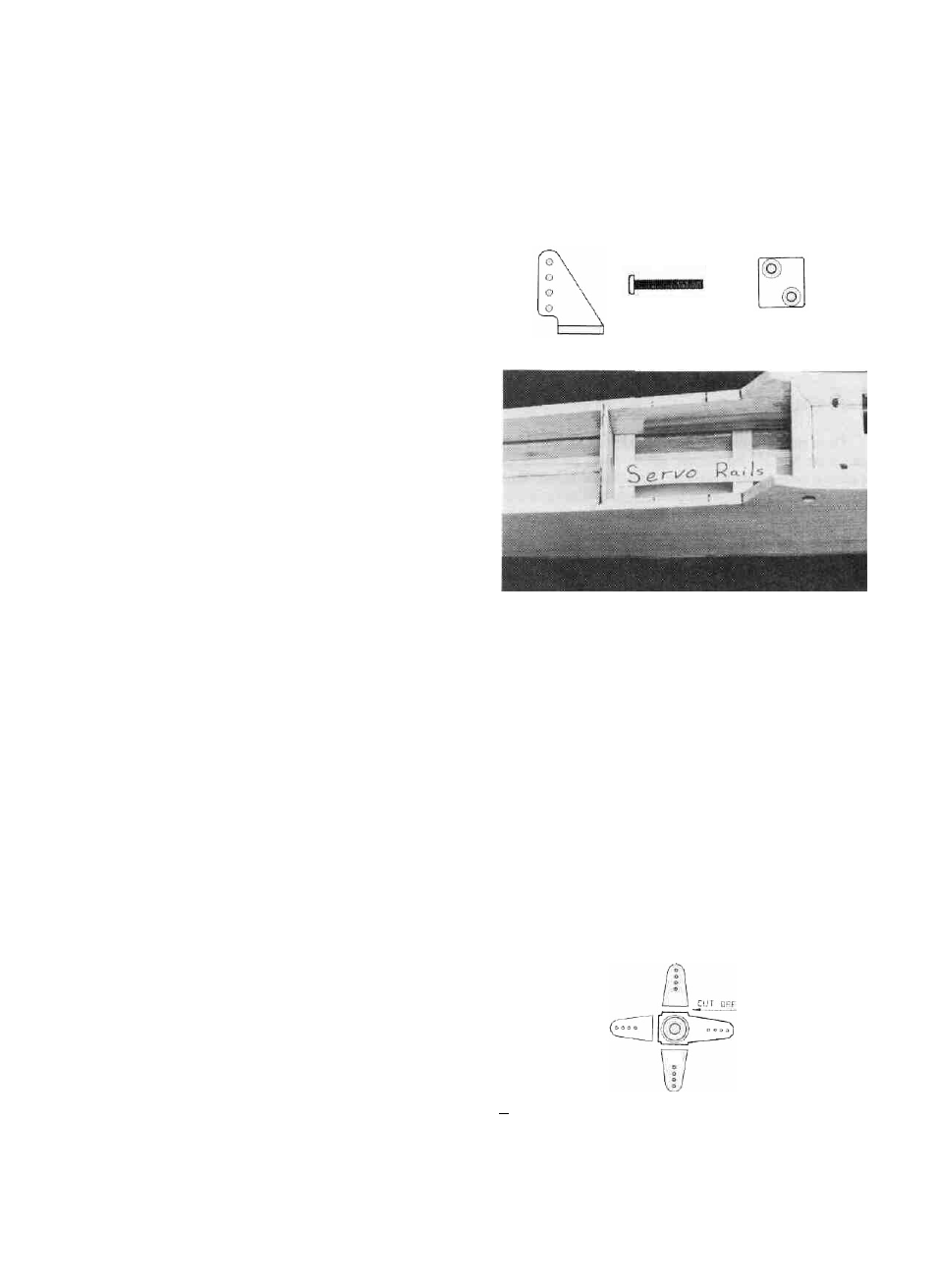
D 3. Cut two 1/4" x 3/8" Basswood Servo Rails (SPT1F14)
2-1/16" long. Slide them into the slot between formers F4 and F5
(Cut two more for between F3 and F4 if you are installing
spoilers). Slide one all the way forward and glue it in place with
med. or thick CA. Slide the other servo rail all the way to the back.
Do not glue it yet! Position one of your servos in place and use
it to position the rear servo rail. Do not push the rear servo rail
up light against the servo but rather leave about a 3/32" gap
between the servo "body" and the rear servo rail. This will give
you enough room to put the servos in and out without removing
the rails. Glue the rear servo rail in place.
INSTALL RADIO GEAR
D 1. Read and follow the instructions that came with your
radio to install or charge the batteries and get the servos ready for
mounting. Plug the servos and the battery pack into the receiver
and turn on the transmitter first and then the receiver. Adjust the
trim levers to their neutral positions and allow the servos to return
to their neutral positions.
D 2. Tack glue the Nylon Control Horns (NYLON03) in
place on the rudder and elevator with a drop of thin CA. Use the
D 4. Position the rudder and elevator servos together in the
middle of the rails and mark where the holes for the servo
mounting screws should be drilled. Remove the servos and drill
1/16" holes where the marks are. Install the servos, with the wires
exiting toward the receiver using the servo mounting screws that
came with the radio.
D 5. Cut three "arms" off of two X-type servo horns using wire
cutting pliers or a razor saw as shown in the sketch. Install the
44