Skip to step 22 when, Wing panel – Great Planes Spirit 100 Sailplane Kit - GPMA0550 User Manual
Page 25
D
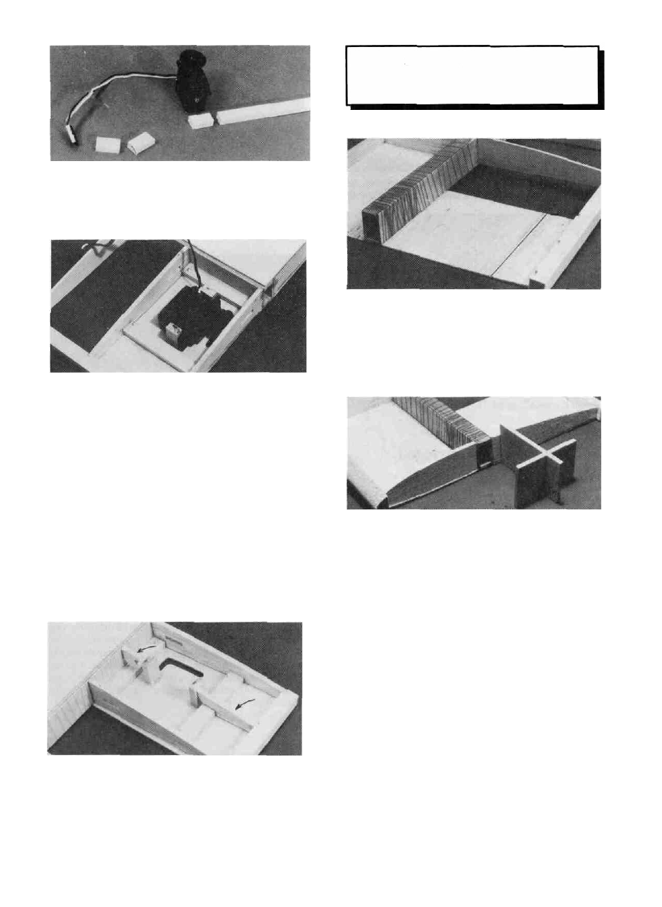
D 20G Measure the width of your servos and cut six Wing
Servo Rails from the 3/16" x 3/8" x 25" Basswood Servo Rail
Strip (SPT1F14) that are as long as your servo is wide.
SKIP TO STEP 22 WHEN
CONSTRUCTING THE LEFT
WING PANEL!
DD 21. Locate one of the 1/16" x 3" x 30" Balsa Sheets
(SPRTW17) and cut o f f three pieces 3" long. Slide one of the
sheets in place behind the joiner box and glue it in place with med.
or thick CA. Cut another piece to fit between the first sheet and
the sub TE and glue it to the first sheet, and the TE.
D D 20H. Position the flap servo so the output horn is cen-
tered in the slot. Look down the wing to make sure the servo does
not extend past the lop of the W1B ribs. If it does you can move
the servo forward and enlarge the slot to accommodate it. Put a
drop of med. or thick CA on one end of two of the wing servo rails
and glue them in place next to the servo mounting flanges.
Remove the servo and add med. or thick CA around the rails to
securely glue them in place.
DD 201. Remove the hatch from the wing and drill 1/16"
holes in the rails for the servo mounting screws and mount the flap
servo flat against the hatch using the screws provided with the
radio.
D D 20J. Replace the hatch with the servo installed and
check to make sure the servo rails do not extend past the top of the
two W1B ribs. If they do, sand them down until they don't.
D D 22 Punch out three W 1 A ribs and three W1B ribs
(SPT1W06) and t e s t f i t the end W1A and W1B ribs into position.
A little sanding may be necessary to make them fit properly They
should be tilted in (towards the tip) at the top using the slanted end
of the rib gauge to give them the correct angle. Glue these ribs into
place using med or thick CA. NOTE: The W1B ribs have
already been installed on the left wing panel.
D D 20K. Cut the remaining W1B rib to fit behind the servo
and glue it in place. If your installation permits, install part of the
rib in front of the servo. Lightly sand the ribs to remove any high
spots.
D D 23. Position the 1/4" x 1-1/8" x 2-7/8" Ply Front Wing
Bolt Plate (SPT1W27) next to the template on the plan. Use the
measurements given to mark where to drill the hole. Drill a
13/64" hole at the mark Notice the hole is off-center.
SKIP THIS STEP IF YOU ARE BUILDING A
RUBBER BAND ON WING.
D D 24. Test fit the front wing bolt plate in place against the
W1A rib. It should be centered up and down on the LE and it
should be parallel to the work surface, with the hole off-center
towards the root of the wing. Sand it, i f necessary, to aclncve a
good fit between the LE and the joiner box. When satisfied with
25