Kenwood TM-255E User Manual
Page 16
Attention! The text in this document has been recognized automatically. To view the original document, you can use the "Original mode".
2 GEniNG ACQUAINTED
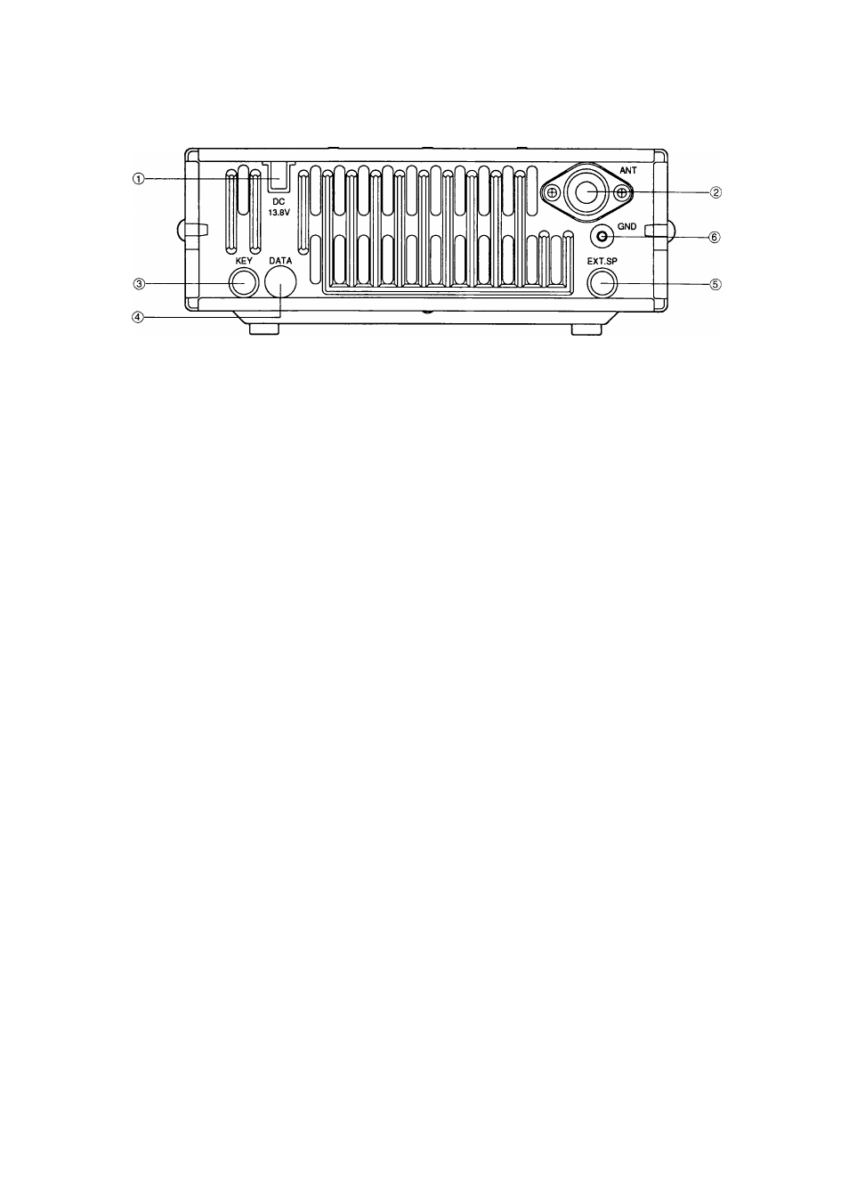
REAR PANEL
0
Power Input DC 13.8 V
Connect a 13.8 V DC power source {pages 2 and 3}.
You can use either a 12 V vehicle battery or a
regulated DC power supply with the supplied DC
cable. The TM-255 draws less than 13 A and the
TM-455 draws less than 15 A at full transmitter output
power.
0 ANT
Connect an external antenna designed for operation
on the same band as this transceiver (pages 2 and 4}.
When making test transmissions, connect a dummy
load in place of the antenna. The antenna system or
load should have an impedance of 50 ohms. Accepts
a male PL-259 coaxial plug.
0 KEY
Connect a key or electronic keyer for CW operation.
Accepts a 3.5 mm diameter mono (2-conductor) plug.
Always turn the transceiver power OFF before
inserting the key plug to avoid momentarily
transmitting as the plug is inserted. See page 5 for
connection details.
0
DATA
Connect a Terminal Node Controller (TNC) for Packet
operation. Accepts a 6-pin mini DIN plug. Also can
be used to control external equipment such as a linear
amplifier. See page 5 for further details.
0
EXT. SP
Connect an optional 8 Q external speaker for clearer
audio (page 4}. Connecting an external speaker cuts
off audio automatically to the internal speaker.
Accepts a 3.5 mm diameter (2-conductor) plug.
© GND
Connect a heavy gauge wire or copper strap between
the ground terminal and the nearest earth ground
(pages 2 and 4}. Do not connect the ground wire to
either your house electrical wiring, or gas or water
pipes. A well-grounded transceiver will reduce the
risk of interference to television or broadcast radio
receivers. It can also reduce receiver noise caused
by static discharges.