Kenwood TM-255E User Manual
Page 13
Attention! The text in this document has been recognized automatically. To view the original document, you can use the "Original mode".
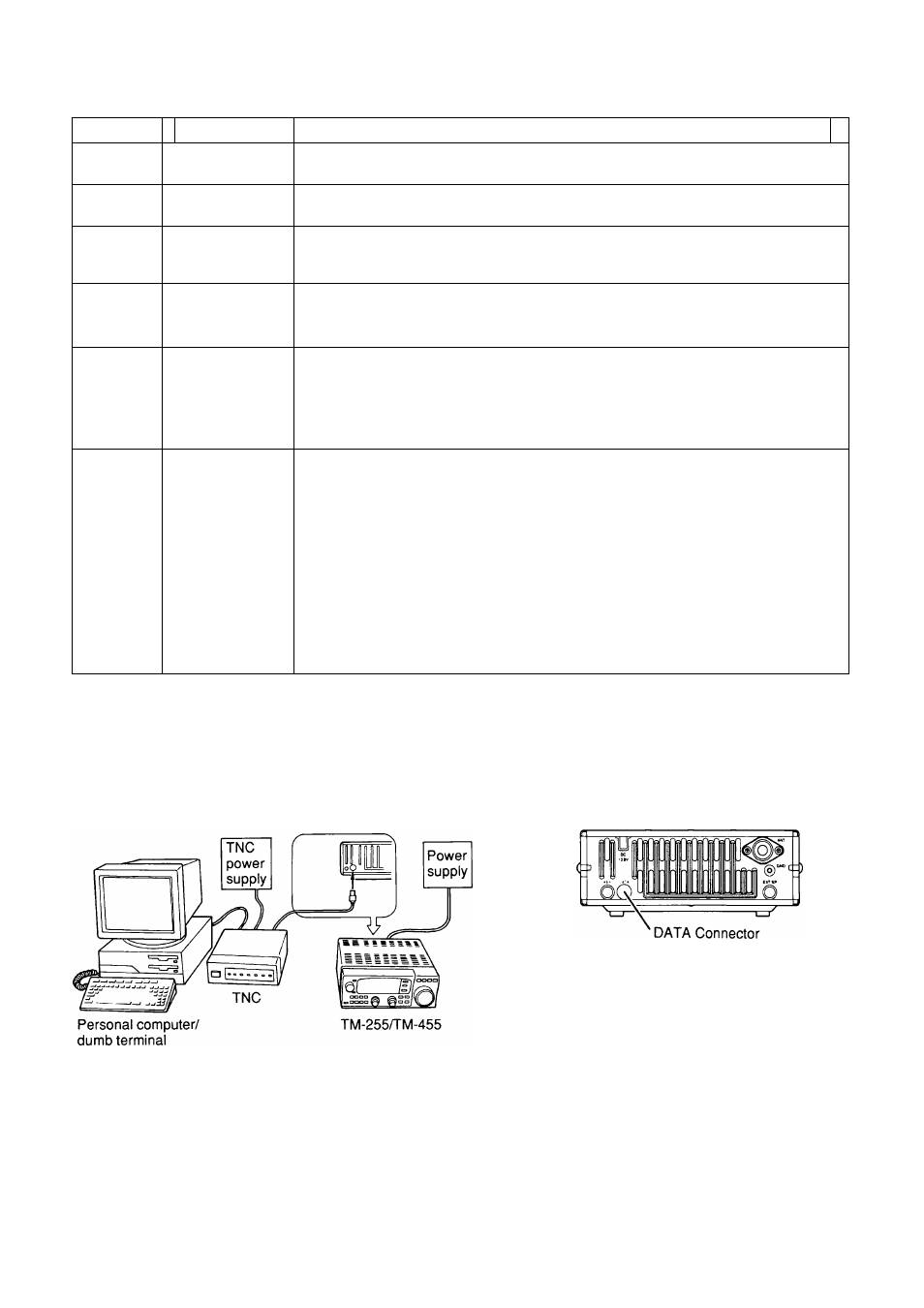
1 INSTALLATION AND CONNECTION
■ DATA Connector Pinout
Pin No.
Pin Name
Function
1
PKD
Packet Data (input)
• Transmit data from TNG to transceiver
2
DE
Data Earth
• Ground for TNG output
3
PKS 1
Packet Standby
• TNG can use this pin to inhibit the transceiver microphone input while transmitting
packet signals.
4
PR9
FM Demodulator Output
•
For 9600 bps Packet operation
•
Output Level: 500 mVp-p/10 kQ
5
PR1
Demodulator Output
•
For 1200 bps Packet and RTTY operation
•
Audio output is taken before the VOL control
(VOL control has no effect on audio level)
•
Output level: 300 mVp-p/10 kO
6
SQC
Squelch Control or Relay Output ^
Squelch Control
•
Inhibits TNG data transmit while transceiver squelch is open. This prevents
interference to voice communications on the same frequency and unwanted retries.
•
Output level
Squelch open: +5 V (HIGH)
Squelch closed: 0 V (LOW)
Relay Output
•
Alternatively, provides a relay output for accessories such as a linear amplifier.
•
The output switches to GND during transmit.
•
Current rating: 500 mA maximum
■' It is not necessary to disconnect the microphone if using the DATA connector. The TNG drives this pin LOW which mutes
the microphone.
2 Switch selectable: Set internal switch to "PSQ" for Squelch Control or "RL" for Relay Output {page 47}.
Transceiver
rear panel