Preparation for fixed station operation, Preparation for mobile operation – Kenwood TM-255E User Manual
Page 10
Attention! The text in this document has been recognized automatically. To view the original document, you can use the "Original mode".
IGNITION NOISE
This transceiver has been designed with a Noise
Blanker to filter ignition noise. However, some cars
may generate excessive ignition noise, if there is
excessive noise, use suppressor spark plugs (with
resistors), or take other countermeasures as may be
required to reduce these undesired electrically
generated noises.
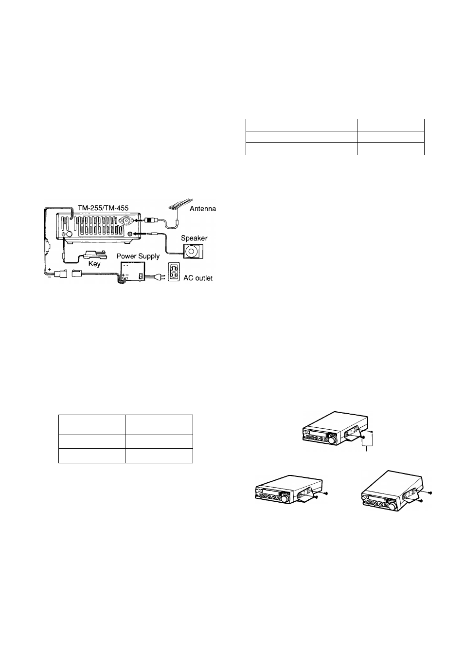
PREPARATION FOR FIXED STATION
OPERATION
The following diagram illustrates how to connect the
cables to the rear of the transceiver. Connect the
cables securely so they will not come loose if pulled.
DC POWER SUPPLY CONNECTION
In order to use this transceiver for fixed station
operation, you will need a separate 13.8 V DC power
supply that must be purchased separately. DO NOT
directly connect the transceiver to an AC outlet! Use
the supplied DC power cable to connect the
transceiver to a regulated power supply. Do not
substitute a cable with smaller gauge wires.
The following table lists the current consumption for
each type of transceiver. Any regulated DC power
supply used should have a current rating higher than
listed in the table.
Transceiver
Mode!
Current
Consumption
TM-255
Less than 13 A
TM-455
Less than 15 A
Plug the connectorized end of the DC power cable
into the DC 13.8 V connector on the rear panel of the
transceiver, and connect the other end of the cable to
the regulated power supply. The red wire must be
connected to the positive (+) terminal and the black
wire to the negative (-) terminal.
Note:
♦
Suitable regulated DC power supplies include the PS-33 and
PS-53. All are available as accessories. Choose a power
supply with a current rating larger than the current requirements
of the transceiver.
♦
Before connecting the DC power supply to the transceiver, be
sure to switch the transceiver and the DC power supply off.
♦
Do not plug the DC power supply into an AC outlet until you
make all connections.
1
INSTALLATION AND CONNECTION
Replacing Fuses
If the fuse blows, determine the cause then correct
the problem. After the problem is resolved, only
then replace the fuse. If newly installed fuses
continue to blow, disconnect the power plug and
contact your dealer or nearest Service Center for
assistance.
Function
Fuse Current
Transceiver Power Cable
15 A
DC Power Cable
20 A
CAUTION: Only use fuses of the specified type and rating.
■ Installation Example
For a deluxe installation, take the time to install the
transceiver in the mounting bracket. The diagram
offers some mounting suggestions.
Added benefits of using the mounting bracket in
your fixed station include the following:
• You can angle the transceiver for best visibility
from your operating position.
• The transceiver remains stationary when you
attach connectors or use any of the controls.
• The transceiver is quickly detachable from the
bracket if you want to move it to your mobile or
any other alternate operating position.
• The bracket eliminates the risk of anybody
bumping the transceiver off your operating
desk.
If you decide to mount the transceiver in a
horizontal plane instead of angling it up or down,
use the top or middle row of mounting holes on the
bracket. The bottom row of holes cannot be used
to mount the transceiver horizontally.
Use the wrench to
tighten the screws.