Kenwood TM-255E User Manual
Page 11
Attention! The text in this document has been recognized automatically. To view the original document, you can use the "Original mode".
1 INSTALLATION AND CONNECTION
ANTENNA CONNECTION
The type of the antenna system, consisting of the
antenna, ground, and feed, will greatly affect the
successful performance of the transceiver. Use a
properly adjusted 50 ohm antenna of good quality
designed for operation at 144 MHz or 430 MHz to let
your transceiver perform at its best.
Install low-loss 50 ohm coaxial cable and a first quality
connector for the connection to the transceiver. For
longer feed line runs, especially for operation at UHF
frequencies, you might consider investing in air-
dielectric transmission line. The lower loss can make
a significant difference for those interested in weak
signal operation. In all cases, match the impedance
of the feed line and antenna so that the SWR is
minimum. Generally, an SWR measurement of 1.5:1
or less is considered satisfactory. All connections
must be clean and tight. Coupling the antenna to the
transceiver via feed line having an impedance other
than 50 ohms reduces the efficiency of the antenna
system. It also can cause interference to nearby
broadcast television receivers, radio receivers, and
other electronic equipment.
CAUTION:
♦
All fixed stations should be equipped with a lightning arrester to
reduce the risk of fire, electric shock, and transceiver damage.
♦
Transmitting without an antenna or other matched load
connected may damage the transceiver. Always connect the
antenna to the transceiver first before transmitting.
GROUND CONNECTION
At the minimum, a good DC ground is required to
reduce the risk of electric shock, and to prevent
interference to other electronic equipment. For
superior communications results, a good RF ground is
required against which the antenna system can
operate. Both of these conditions can be satisfied by
providing a good earth ground for your station. Bury
one or more ground rods, or a large copper plate
under the ground, and connect this to the transceiver
GND terminal. Use heavy gauge wire or a copper
strap, cut as short as possible, for this connection. As
for antenna work, all connections must be clean and
tight.
CAUTION: DO NOT use a gas pipe, an electrical conduit, or a
plastic water pipe for a ground. All are dangerous or poor
practices.
ACCESSORY CONNECTIONS
EXTERNAL SPEAKER
Use an external speaker with 8 ohms impedance.
The jack accepts a 3.5 mm diameter mono (2-
conductor) plug.
MICROPHONE
To communicate in the voice modes, connect a
microphone having an impedance of 600 ohms.
■ Installing the Microphone
Before beginning to install the microphone, switch
OFF the POWER switch.
1 Press the Release button on the left side of the
Front Panel to unlock the panel. Carefully pull
the Front Panel forward from the left, then
remove it completely.
• Handle the Front Panel carefully to avoid
applying excessive force to the thin cable
joining the Front Panel to the Main Unit.
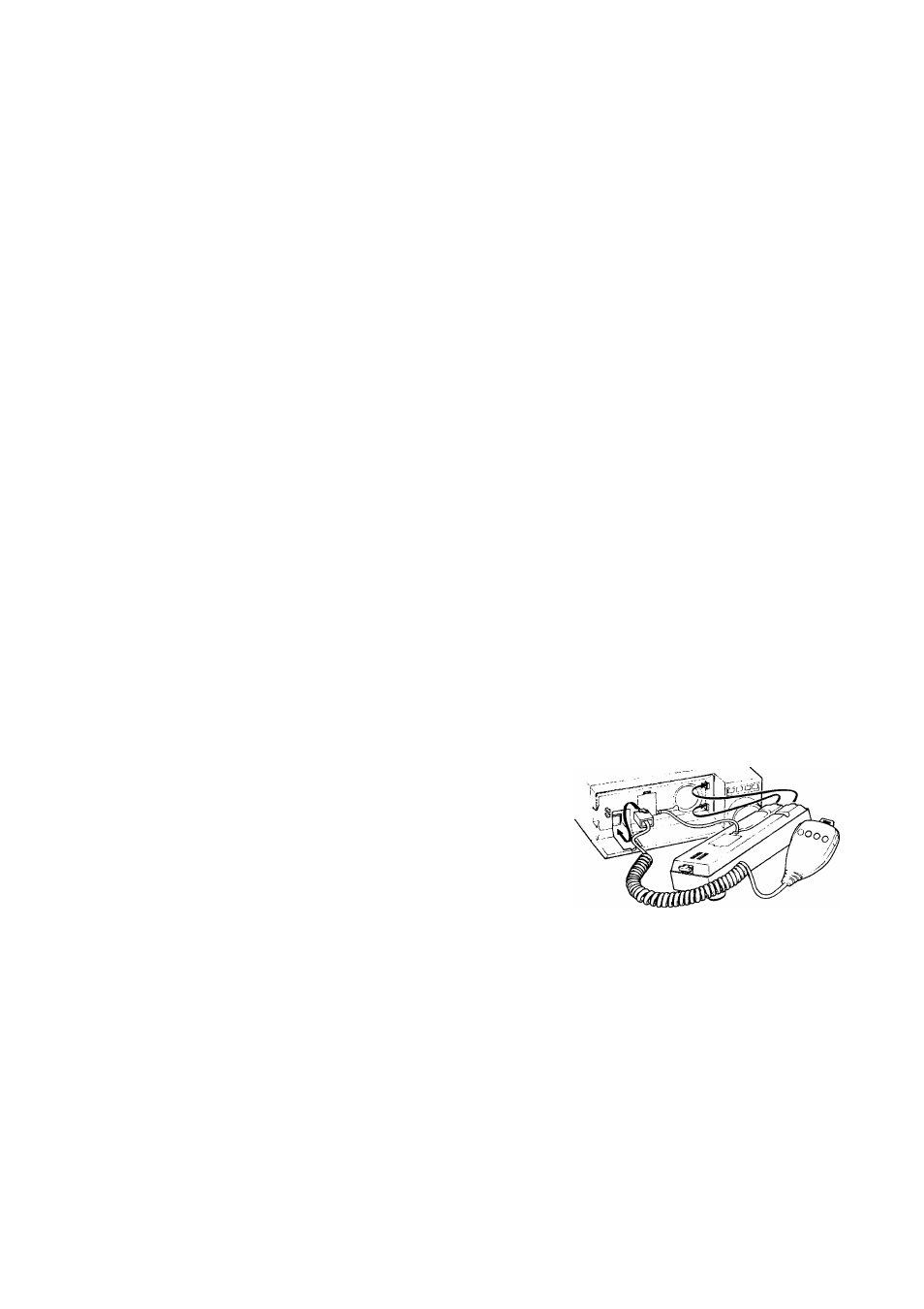
2 Insert the 8-pin modular microphone connector,
keeping its locking tab upward, into the jack
located at the lower left corner of the Main Unit
front. Push gently inward until the tab "clicks"
into place.
• If using a microphone that does not have a
modular plug, use a conversion cable. For
example, the MJ-88 cable accepts an 8-pin
microphone plug at one end. The other end
has a modular plug that mates with this
transceiver.
3 Reinstall the Front Panel.
• Check that the bushings holding the thin
cable are in place, and the microphone
cable is in the groove before closing the
Front Panel.
• Press firmly on the Front Panel so the
Release button locks.