Electrical connections (cont.), H 3-wire power cord installation, H 4-wire power cord installation – GE CS975SDSS User Manual
Page 43: Installation instructions, Electrical connections, A warning, Cont.) h 3-wire power cord installation
Attention! The text in this document has been recognized automatically. To view the original document, you can use the "Original mode".
Installation Instructions
ELECTRICAL CONNECTIONS
(CONT.)
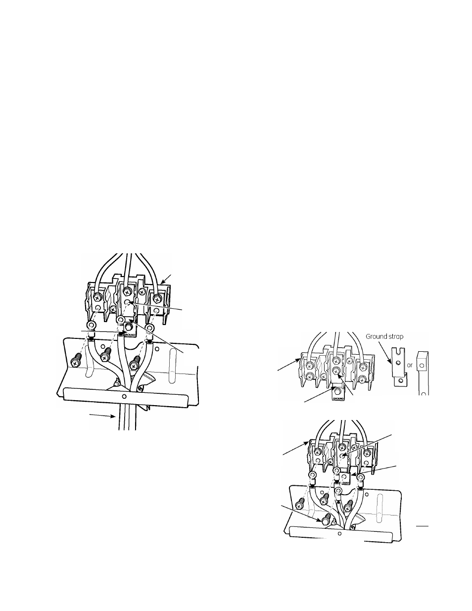
H 3-WIRE POWER CORD INSTALLATION
A WARNING:
The neutral or ground
wire of the power cord must be connected
to the neutral terminal located in the center
of the terminal block. The power leads must
be connected to the lower left and the lower
right terminals of the terminal block.
Remove the 3 lower terminal screws from
the terminal block. Insert the 3 terminal screws
through each power cord terminal ring and
into the lower terminals of the terminal block.
Be certain that the center wire (white/neutral)
is connected to the center lower position of
the terminal block. Tighten screws securely
into the terminal block.
DO NOT remove the ground strap
connection.
Terminal
block
(appearance
may vary)
Neutral
terminal
Ground plate
Ground
strop
Power cord
E Skip to Step 8 and proceed with
the installation.
H 4-WIRE POWER CORD INSTALLATION
A WARNING:
The neutral wire of the supply
circuit must be connected to the neutral
terminal located in the lower center of the
terminal block. The power leads must be
connected to the lower left and the lower right
terminals of the terminal block. The 4th
grounding lead must be connected to the frame
of the range with the ground plate and the
ground screw.
E Remove the 3 lower terminal screws from the
terminal block. Remove the ground screw and
ground plate and retain them.
Cut and discard the ground strap.
DO NOT DISCARD ANY SCREWS.
E Insert the one ground screw into the power cord
ground wire terminal ring, through the ground
plate and into the frame of the range.
E Insert the 3 terminal screws (removed earlier)
through each power cord terminal ring and into
the lower terminals of the terminal block. Be
certain that the center wire (white/neutral) is
connected to the center lower position of the
terminal block. Tighten screws securely into the
terminal block.
Before
Terminal
block
Ground strap
Neutral
terminal
Af^er
Terminal
block
Ground'
screw
Neutral
terminal
Ground plate
(grounding
to range)
o
GROUND
iHT^
[3 Skip to step 8 and proceed with the installation.
43