Receiver & battery installation, Pilot platform installation – Carl Goldberg GPMA1956 Eagle 2 ARF User Manual
Page 30
30
22.
Check the stab and elevator to make sure
they are in a straight line. If necessary, adjust the elevator
up or down by screwing the snap link in or out. Replace
the center screw into the servo.
1.
Collect the following required items :
(1)
Radio receiver
(1)
Aileron extension WIRE
(1)
Receiver battery
(1)
Remaining piece of foam rubber
(2)
Rubbers bands
(1)
T-pin
2.
Place the receiver near the edge of the
foam rubber and mark a cut line, so the foam area is ½"
larger than the receiver.
3.
Open the antenna and stretch it out.
4.
Cut the foam and wrap it around the
receiver, securing with a rubber band. Leave the receiver
sticking out, so that you are able to plug the servos in with-
out interference.
5.
Following the instructions and diagrams for
your radio, plug all the servo wires into the receiver. Take
care to connect each servo wire to the proper device, i.e.
to connect the rudder servo to the rudder plug, the elevator
servo to the elevator plug, and the aileron extension wire
to the aileron plug.
6.
Connect one switch plug to the battery
location on the receiver.
7.
With the remaining foam, cut and wrap the
battery pack, just as you did with the receiver.
8.
Plug the battery wire into the switch wire.
9.
Tuck the battery and the receiver all the
way into the foam wrapping.
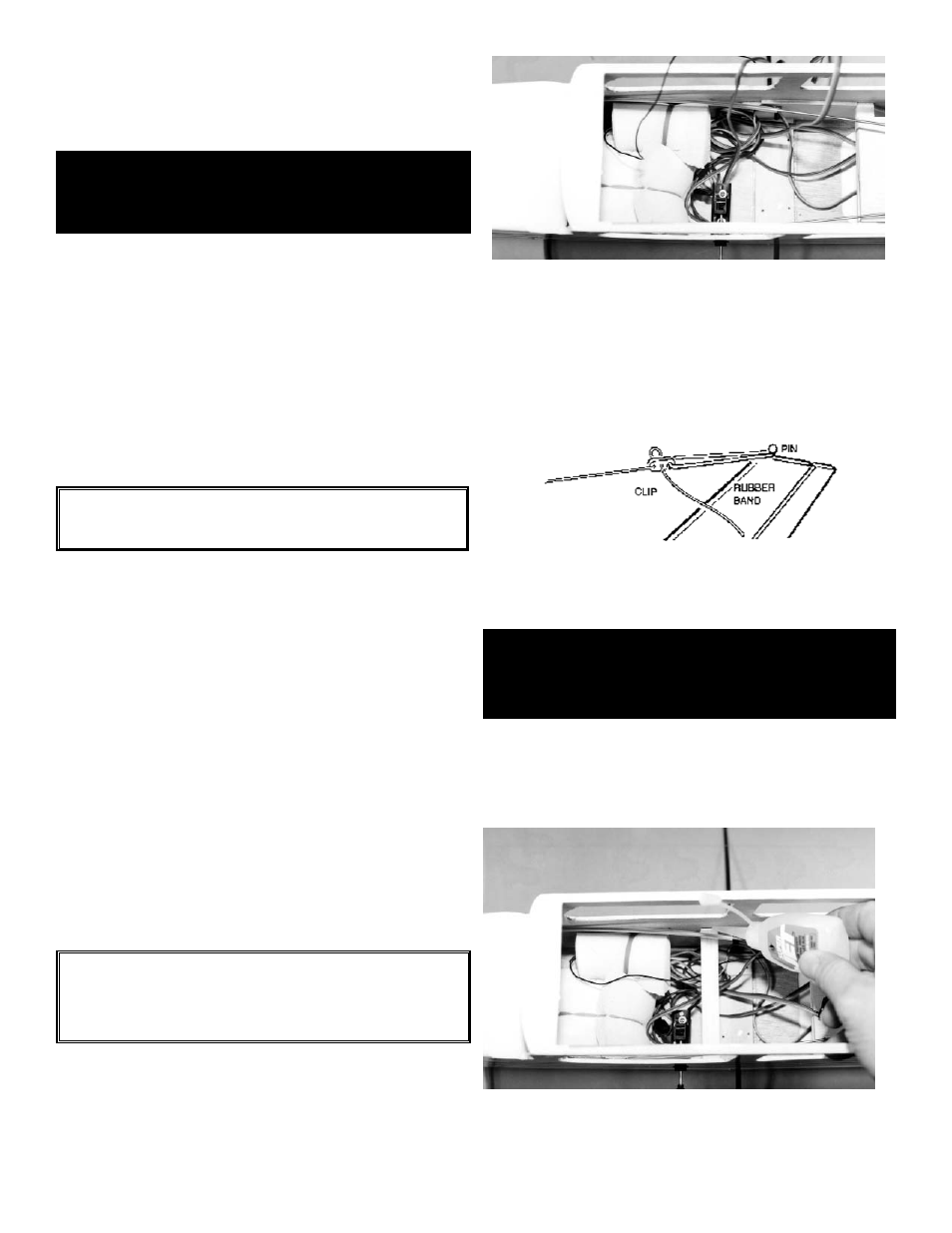
Place both the receiver and the battery
pack into the bottom of the fuselage just behind the front
cabin former. Route the receiver antenna through the fuse-
lage cabin and out the top of the fuselage behind the wing.
Both the aileron extension wire and the charging jack wire
should be sticking outside of the fuselage.
10.
Take a pin and push it into the top of your
fin with a slight lean towards the back. Attach the rubber
band to the end of the antenna and put the rubber band
around the pin. Pull tight on the antenna.
RECEIVER & BATTERY
INSTALLATION
NOTE: Never change the antenna length. The
length is tuned to the receiver.
NOTE: The remaining wire on the switch is
the charging jack and needs to be KEPT
ACCESSIBLE.
PILOT PLATFORM
INSTALLATION
1.
Collect the following required Items:
(1)
¼" x ½" x 3-5/8" wood rail
(1)
Plywood pilot platform
(1)
#2 x 5/16 sheet metal screw
2.
Place the ¼" x ½" x 3-5/8" wood rail inside
the fuselage, fitting it into the notch on the side doublers.
CA glue in place.