Hatch installation throttle pushrod installation – Carl Goldberg GPMA1956 Eagle 2 ARF User Manual
Page 19
19
1.
Collect the follow parts:
(1)
Hatch hold-down
(3)
#2 x 3/16" sheet metal screw
(1)
Hatch cover
2.
Position the hatch cover on the fuse.
Press hold-down against the front of the firewall and up
against the bottom of the hatch cover, as shown. The
"straight action" end should point towards the fuse bottom.
Tape in position on firewall.
Remove the hatch cover and apply CA
glue to the hold down. Replace the hatch cover on fuse,
gluing it to the hold-down. Allow to dry.
3.
When dry, remove the hold-down/hatch
assembly from the firewall and drill two 1/16" pilot holes.
Secure the hold-down to the hatch with the two 3/16"
screws.
4.
Reposition the hatch on the fuse. Mark
the location for the #2 screw and install the screw on the
firewall, as shown. Be sure to leave enough of the
unthreaded shank to engage the hold-down. Snap on and
off several times, to make sure the screw is properly
secured.
1.
Collect the following parts:
(1)
1/8" x 10-1/2" nylon tube
(1)
.072 x 19" threaded rod
(1)
nylon mini-snap link
2.
Remount the engine into the front of the
fuselage.
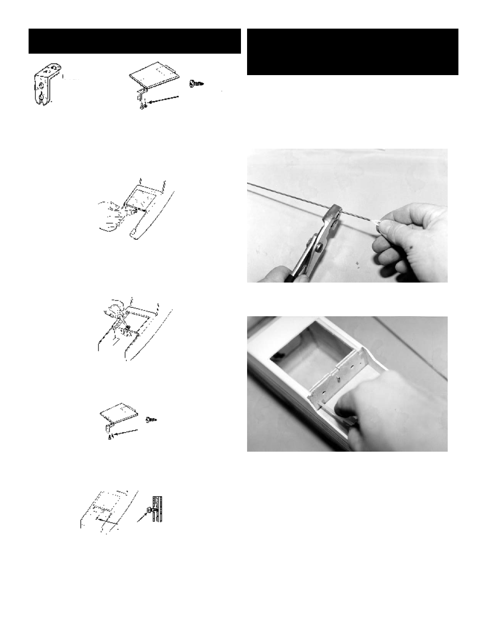
3.
Screw the mini-snap link onto the threaded
rod.
4.
Referring to the photo, start at the hole in
the right side of the firewall and slide the throttle guide
tube into the fuselage and through the upper notch on the
side of the front cabin former. The nylon guide tube should
protrude 1/8" out of the firewall as shown in the following
drawing.
HATCH INSTALLATION
THROTTLE PUSHROD
INSTALLATION
#2 Shoulder Screw as Mounted in Firewall
Note: Unthreaded Shank
#2 x 3/16 Sheet
Metal Screw
#2 x 3/16 Sheet
Metal Screw
Hatch
Hold - Down
“Straight Action”
End