Carl Goldberg GPMA1956 Eagle 2 ARF User Manual
Page 21
21
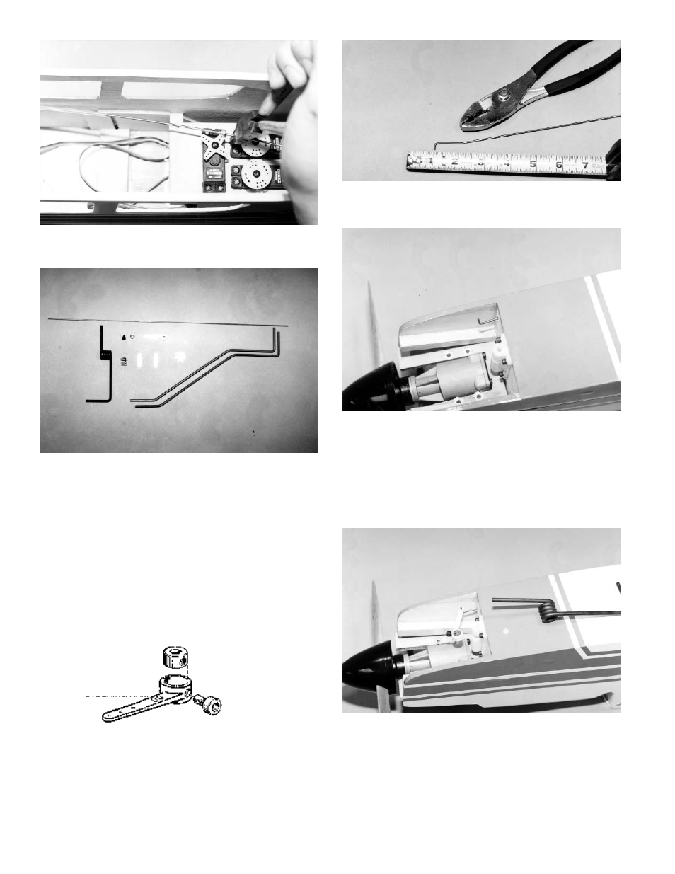
15.
Cut the excess throttle pushrod wire stick-
ing out beyond the pushrod connector. Leave about a ½"
of wire, to allow for adjustments.
1.
Gather the necessary items:
(1)
Fuselage
(2)
Main gear wire struts
(2)
¾" landing gear straps (measure hole to
hole)
(4)
#2 x 5/16 sheet metal screws
(1)
Nylon nosegear steering arm
(1)
Wheel collar
(1)
6-32 x 3/16 socket head screw
(1)
5/32 nosegear strut
(1)
Nylon snap nut
(1)
16-3/4" wire
2.
Making sure the side holes are aligned,
press the steel collar into the pocket in the nylon steering
arm.
Thread the #6-32 x 3/16" socket head
screw in a few turns.
3.
Make a ¼" bend at one end of the 16-3/4"
wire. Then, referring to the photo, bend the wire at approxi-
mately a 20° angle about 1" back from the first bend.
4.
With the fuselage bottom-side up, insert
the unbent end of the wire into the hole on the opposite
side from the throttle pushrod and nearest the bottom of
the fuselage.
5.
With the fuselage right side up, make sure
the pushrod is going through the side slot closest to the
fuselage bottom in the front cabin former.
6.
With the fuse UPSIDE DOWN, Place the
wire on the outermost hole on the nylon steering arm.
Fasten the nylon snap nut on the end of the wire to hold
the steering arm in place.
Steel Collar
#6-32 x 3/16 Socket Head Screw
Steering Arm