Carl Goldberg GPMA1956 Eagle 2 ARF User Manual
Page 29
29
16.
Looking down at the top of the fin, make
sure the rudder is in a straight line with the fin. Adjust if
necessary by twisting the snap link in and out.
Examine the nosegear to make sure the
wheel position is straight forward. Adjust, if necessary.
Install the snap nut on the nosegear
pushrod at the servo end.
17.
Mount the snap-link onto the remaining
threaded rod. The end of the rod should show in the mid-
dle of the snap-link.
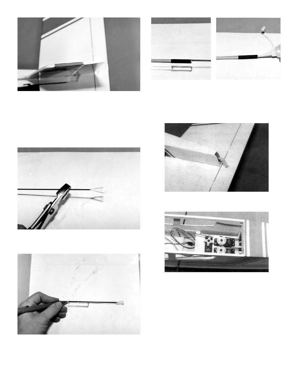
18.
Lay the wire over the Elevator Pushrod
Drawing #2 and mark the location of the bend. Bend the
wire at the mark and cut off to the length on the drawing.
19.
As with the rudder pushrod assembly,
insert the bent wire end into the hole and slot in the
remaining (LONG) wooden pushrod. CA glue the wire in
place and slide the black shrink tubing over the pushrod
assembly. Shrink with a hair dryer and, when the tubing is
tight, glue the edges of the shrink tubing using thin CA
glue.
20.
Thread the pushrod assembly through the
fuselage and exiting out the end, as shown. Attach the
snap link to the outside hole on the elevator control horn.
21.
As before, drill a 1/16" hole in the elevator
wheel. Remove the center screw from the elevator servo
arm and twist the pushrod onto the servo arm.